ESP32 S3 - ILI9341 ILI9488 ST7789 TFT-LCD-Touch-Display mit SPI-Schnittstelle

Lassen Sie uns ein Projekt bauen, das ein vollfarbiges SPI-TFT-Display mit einem ESP32 S3 zum Leben erweckt. Der ESP32 S3 ist ein leistungsstarker Dual-Core-Mikrocontroller mit WLAN, Bluetooth und zahlreichen GPIOs – und sein Hardware-SPI-Bus macht es einfach, ein schnelles TFT-Display mit der vollen vom Panel unterstützten Geschwindigkeit zu betreiben.

Was Sie bauen werden:

  1. Eine verdrahtete Verbindung zwischen einem ESP32 S3 und einem SPI-TFT-Display.
  2. Eine Formen-Demo mit der Zeichen-API von Adafruit GFX.
  3. Ein Beispiel zur Anzeige von Text und Zahlen.
  4. Einen Bitmap-Bildbetrachter, der aus dem Programmspeicher (PROGMEM) liest.
  5. Einen Bitmap-Bildbetrachter, der Bilder von einer SD-Karte liest.
  6. Eine Demo mit benutzerdefinierter externer Schriftart.
  7. Einen Leser für Touch-Koordinaten mit einem XPT2046-Controller.
  8. Eine Touch-Zeichenanwendung (Malen mit dem Finger auf dem Bildschirm).
  9. Eine interaktive Oberfläche mit Touch-Tasten.
  10. Ein Werkzeug zur Kalibrierung des Touchscreens.
  11. Ein Beispiel für einen benutzerdefinierten SPI-Bus mit einem zweiten SPI-Bus des ESP32 S3.

Dieses Projekt behandelt SPI-TFT-LCD-Displays mit und ohne Touch. Es funktioniert mit Panels in 1,3, 1,54, 2,2, 2,4, 2,8, 3,2 und 3,5 Zoll, die von ILI9341-, ILI9488- oder ST7789-Controllerchips angesteuert werden.
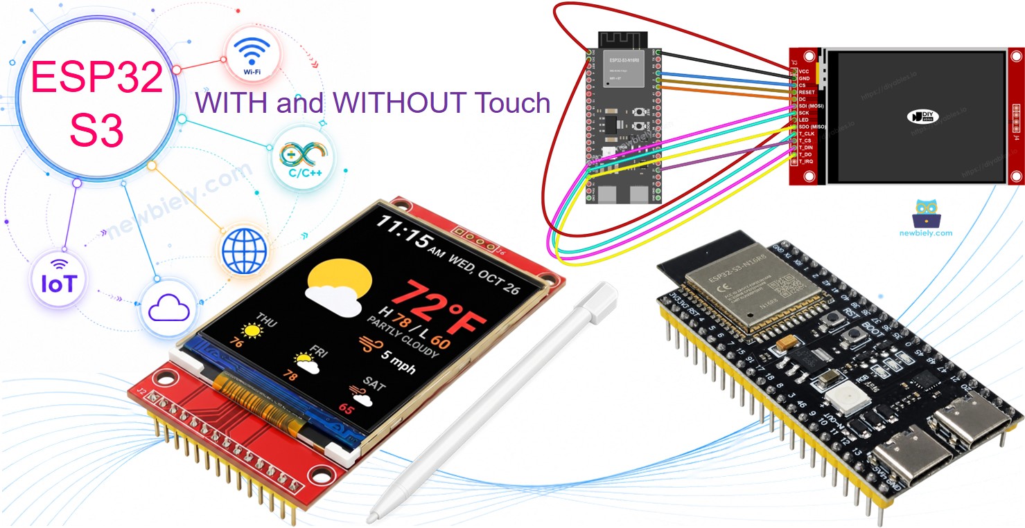
ESP32 S3 TFT-SPI-Display

Erforderliche Hardware

1×ESP32 S3 WROOM N16R8
1×(Alternativ) ESP32 S3 SuperMini Dev Module
1×(Alternativ) ESP32 S3 Uno-form Board
1×(Alternativ) ESP32 S3 Camera Board
1×USB-Kabel Typ-A zu Typ-C (für USB-A PC)
1×USB-Kabel Typ-C zu Typ-C (für USB-C PC)
1×SPI TFT display module
1×Verbindungskabel
1×(Empfohlen) Screw Terminal Expansion Board for ESP32 S3
1×(Empfohlen) Breakout Expansion Board for ESP32 S3
1×(Empfohlen) Power Splitter for ESP32 S3

Oder Sie können die folgenden Kits kaufen:

1×DIYables ESP32 S3 Starter-Kit (ESP32 S3 enthalten)
1×DIYables Sensor-Kit (18 Sensoren/Displays)
Offenlegung: Einige der in diesem Abschnitt bereitgestellten Links sind Amazon-Affiliate-Links. Wir können eine Provision für Käufe erhalten, die über diese Links getätigt werden, ohne zusätzliche Kosten für Sie. Wir schätzen Ihre Unterstützung.

Was ist das SPI-TFT-Display?

Ein SPI-TFT-Modul kombiniert ein Farb-LCD mit einem Treiber-IC, der Zeichenbefehle über einen 4-Draht-SPI-Bus entgegennimmt. Die Bibliothek DIYables_TFT_SPI unterstützt drei gängige Controllerchips, die jeweils unterschiedliche Farbtiefen und Geschwindigkeiten bieten.

Wichtige Spezifikationen

  • ILI9341 - 16-Bit-RGB565-Farbe, bis zu 40 MHz SPI.
  • ILI9488 - 18-Bit-RGB666-Farbe über SPI, bis zu 24 MHz.
  • ST7789 - 16-Bit-RGB565-Farbe, bis zu 40 MHz SPI.

Empfehlung: Wenn Sie noch kein Display gekauft haben, empfehlen wir den Treiber ST7789. Er ist weit verbreitet, läuft mit vollen 40 MHz SPI-Geschwindigkeit und ist die einfachste Wahl für neue Projekte.

Das Zeichnen erfolgt über die Adafruit-GFX-API, die Formen, Text, benutzerdefinierte Schriftarten und Bitmap-Ausgabe umfasst.

Hinweis: Der ESP32 S3 verwendet 3,3-V-Logik. Die meisten SPI-TFT-Module arbeiten mit 3,3 V. Überprüfen Sie vor der Verdrahtung die Spannungsangabe Ihres Moduls.

Pinbelegung

Die meisten SPI-TFT-LCD-Displays haben die folgenden Pins, aufgeteilt auf den Display-Controller, den optionalen SD-Kartensteckplatz und den optionalen XPT2046-Touch-Controller.

Display-Pins:

Pin Funktion
VCC Stromversorgung
GND Masse
CS Chip Select – wird auf LOW gezogen, um das Display am SPI-Bus auszuwählen
DC / RS Daten-/Befehlsauswahl – HIGH für Pixeldaten, LOW für Befehle
RST Hardware-Reset – optional; bei Nichtverwendung mit 3,3 V verbinden
MOSI / SDI / SDA SPI-Dateneingang (MCU → Display)
SCK / CLK SPI-Takt
MISO / SDO SPI-Datenausgang (Display → MCU) – optional bei reiner Anzeigenutzung
LED / BL / BLK Stromversorgung der Hintergrundbeleuchtung – mit 3,3 V oder einem PWM-Pin zum Dimmen verbinden

SD-Karten-Pins (falls Ihre Anwendung auf die SD-Karte zugreifen muss):

Pin Funktion
SD_CS / TF_CS Chip Select der SD-Karte
MOSI / SDI MOSI – Daten von der MCU zur SD-Karte
SCK / CLK SCK – SPI-Takt
MISO / SDO MISO – Daten von der SD-Karte zur MCU

Bei TFT-Displays mit Touch-Unterstützung gibt es zusätzliche Touch-Pins (falls Ihre Anwendung die Touch-Funktion nutzt und das Display sie unterstützt):

Pin Funktion
T_CS Chip Select des Touch-Controllers
T_CLK SCK – SPI-Takt
T_DIN MOSI – Daten von der MCU zum Touch-Controller
T_DO MISO – Daten vom Touch-Controller zur MCU
T_IRQ Touch-Interrupt – optional; signalisiert, wenn der Bildschirm berührt wird

Hinweis: Einige Displaymodule ohne Touch haben ebenfalls die Pins T_CS, T_CLK, T_DIN, T_DO und T_IRQ. Diese sind auf solchen Boards funktionslos – der Touch-Controller-IC ist nicht bestückt. Sie sind vorhanden, weil die Platine dasselbe Layout wie die Touch-Version verwendet, um die Anzahl der Fertigungsvarianten zu reduzieren.
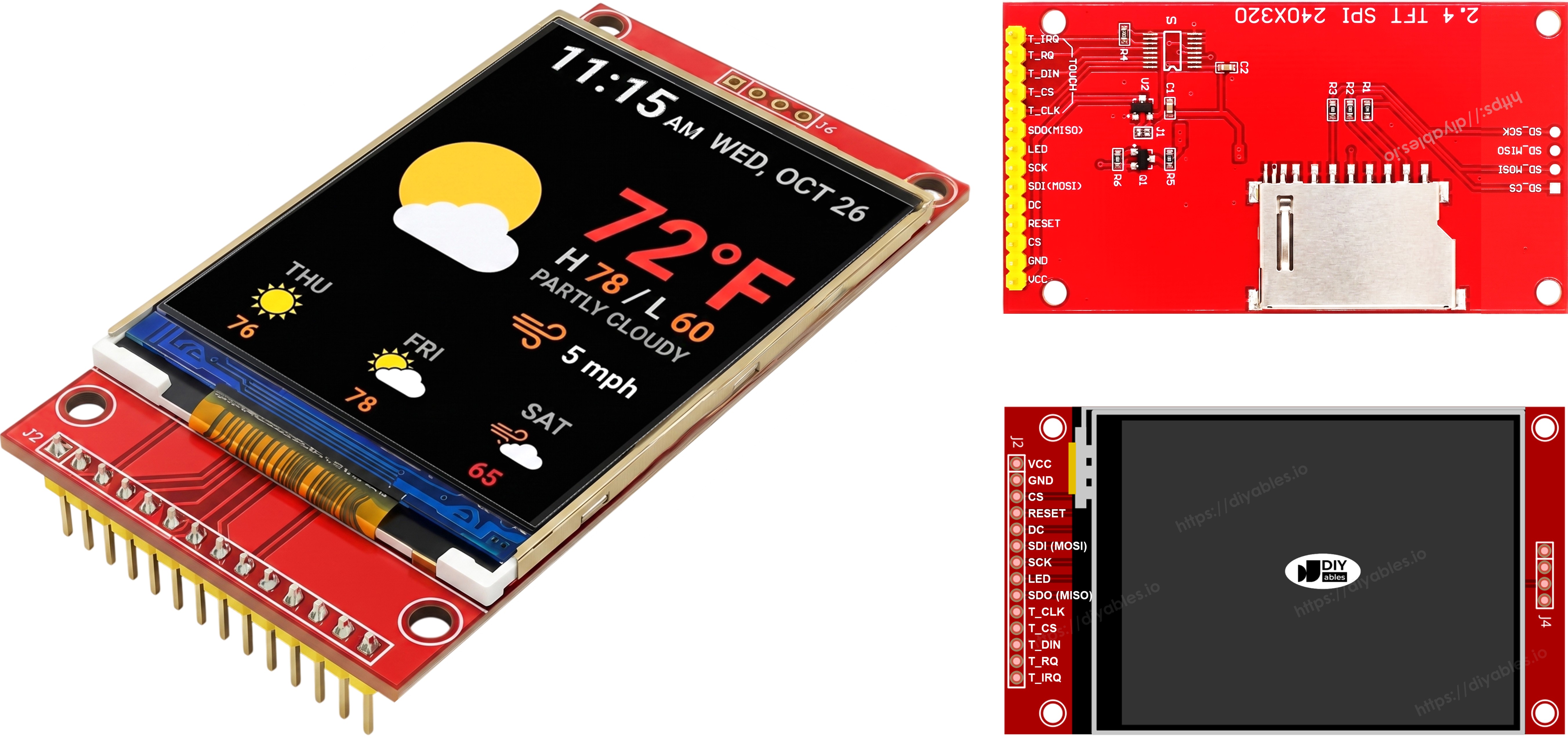
Pinbelegung des TFT-SPI-Displays

Verdrahtungsdiagramm

Hinweis – SDO (MISO) ist optional: Die SDO-Leitung (MISO) überträgt nur Daten vom Display zurück zum Board. Keiner der Beispielcodes in diesem Tutorial liest Daten vom Display, daher kann dieser Pin unverbunden bleiben. Bei Modulen, bei denen der Touch-Controller denselben SPI-Bus nutzt, kann eine angeschlossene SDO-Leitung die Kommunikation stören, daher wird empfohlen, sie nicht anzuschließen.

Ohne Touch

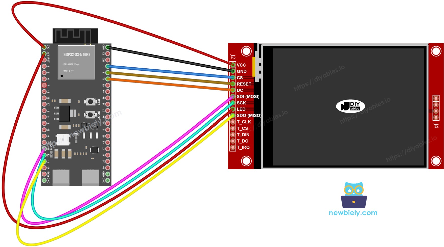
Verbinden Sie MOSI mit GPIO11, SCK mit GPIO12 und MISO mit GPIO13 des ESP32 S3. CS, DC und RST können beliebige freie GPIOs sein – in den Beispielen werden GPIO1, GPIO42 und GPIO2 verwendet.

Display:

TFT-Pin ESP32 S3 Pin Beschreibung
VCC 3.3V Stromversorgung (nur 3,3 V)
GND GND Masse
CS GPIO1 Chip Select
DC / RS GPIO42 Daten-/Befehlsauswahl
RST GPIO2 Reset (optional)
MOSI / SDI GPIO11 Hardware-SPI MOSI
SCK GPIO12 Hardware-SPI-Takt
MISO / SDO GPIO13 Hardware-SPI MISO (optional)
LED / BL 3.3V Stromversorgung der Hintergrundbeleuchtung

SD-Karte (falls Ihre Anwendung auf die SD-Karte zugreifen muss):

SD-Pin ESP32 S3 Pin Beschreibung
SD_CS / TF_CS beliebiger freier GPIO Chip Select der SD-Karte
MOSI / SDI GPIO11 Gemeinsam mit Display-MOSI (GPIO11)
SCK / CLK GPIO12 Gemeinsam mit Display-SCK (GPIO12)
MISO / SDO GPIO13 Gemeinsam mit Display-MISO (GPIO13)
Verdrahtungsplan ESP32 S3 TFT-SPI-Display ohne Touch

Dieses Bild wurde mit Fritzing erstellt. Klicken Sie, um das Bild zu vergrößern.

Mit Touch

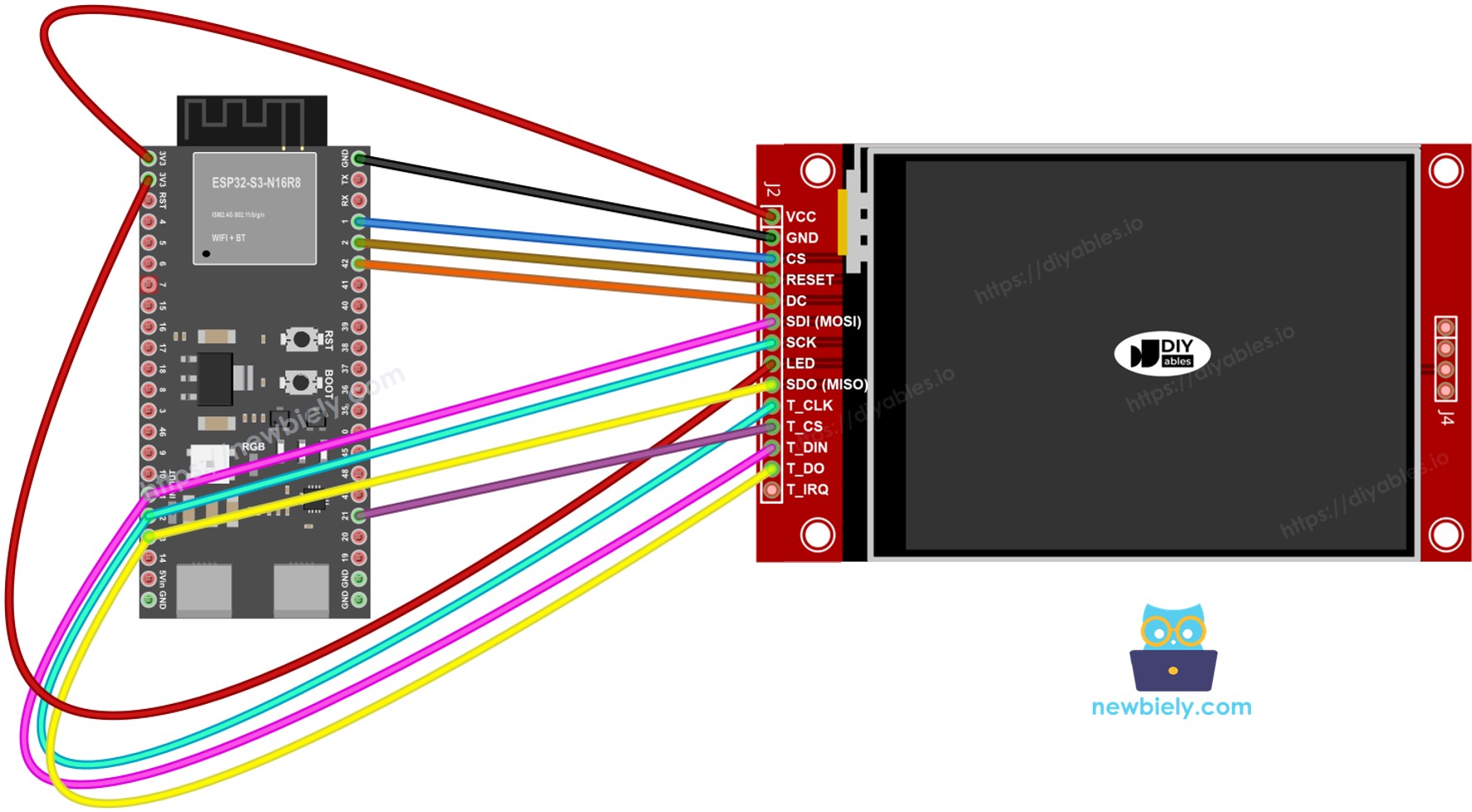
Verbinden Sie den XPT2046-Touch-Controller mit dem SPI-Bus des ESP32 S3, wobei GPIO11, GPIO12 und GPIO13 gemeinsam mit dem Display genutzt werden.

Display:

TFT-Pin ESP32 S3 Pin Beschreibung
VCC 3.3V Stromversorgung (nur 3,3 V)
GND GND Masse
CS GPIO1 Chip Select
DC / RS GPIO42 Daten-/Befehlsauswahl
RST GPIO2 Reset (optional)
MOSI / SDI GPIO11 Hardware-SPI MOSI
SCK GPIO12 Hardware-SPI-Takt
MISO / SDO GPIO13 Hardware-SPI MISO (optional)
LED / BL 3.3V Stromversorgung der Hintergrundbeleuchtung

Touch-Controller (falls Ihre Anwendung die Touch-Funktion nutzt und das Display sie unterstützt):

Touch-Pin ESP32 S3 Pin Beschreibung
T_CS GPIO21 Touch Chip Select
T_IRQ beliebiger freier GPIO Touch-Interrupt (optional)
T_DIN GPIO11 Gemeinsam mit Display-MOSI (GPIO11)
T_CLK GPIO12 Gemeinsam mit Display-SCK (GPIO12)
T_DO GPIO13 Gemeinsam mit Display-MISO (GPIO13)
Verdrahtungsplan ESP32 S3 TFT-SPI-Display mit Touch

Dieses Bild wurde mit Fritzing erstellt. Klicken Sie, um das Bild zu vergrößern.

Wenn Ihre MCU zwei oder mehr Hardware-SPI-Schnittstellen hat, können Sie jedem Peripheriegerät (Display, SD-Karte, Touch-Controller) einen eigenen SPI-Bus zuweisen. Wenn Ihre MCU nur eine Hardware-SPI-Schnittstelle hat, teilen sich alle drei Peripheriegeräte dieselben drei Datenleitungen (MOSI, SCK, MISO). Jedes Peripheriegerät hat einen eigenen CS-Pin, sodass immer nur eines aktiv ist. Die Bibliothek DIYables_TFT_SPI verwaltet sowohl das Display als auch den XPT2046-Touch-Controller über eine einzige API – für die Touch-Seite ist keine separate SPI-Bibliothek erforderlich.

Bibliotheksinstallation

  1. Verbinden Sie das ESP32-S3-Board über seinen USB-C-Anschluss mit Ihrem Computer.
  2. Öffnen Sie die Arduino IDE. Wählen Sie Ihre ESP32-S3-Board-Variante im Board-Menü aus und wählen Sie den richtigen COM-Port.
  3. Öffnen Sie das Panel Libraries.
  4. Suchen Sie nach "DIYables_TFT_SPI". Suchen Sie den Eintrag von DIYables.
  5. Klicken Sie auf Install und bestätigen Sie die Installation aller Abhängigkeiten.
  • Search for DIYables TFT SPI created by DIYables.io and click the Install button.
∞
Newbiely | Arduino IDE 2.3.8
──
☐
✕
File
Edit
Sketch
Tools
Help
ESP32S3 Dev Module
Library Manager
Type:
All
Topic:
All
DIYables TFT SPI by DIYables.io
Works with both touch and non-touch versions of the same SPI TFT modules. Supports ILI9341 (240x320, 16-bit RGB565), ILI9488 (320x480, 18-bit RGB666), and ST7789 (240x320, 16-bit RGB565) displays over SPI. Includes built-in driver for XPT2046 / HR2046 / ADS7843 SPI touch controllers and 4-wire resistive touch panels - no separate touch library required. Use the display-only API for non-touch panels, or add initTouchSPI() to enable touch on modules that include a touch controller. Extends Adafruit GFX for full graphics support. Works with any Arduino-compatible board that has SPI. More info
1.0.3
INSTALL
Newbiely.ino
···
1 void setup() {
Output
Serial Monitor
Ln 1, Col 1
ESP32S3 Dev Module on COM15
1

Projektgrundlage

Der folgende Code bildet den Basis-Sketch für jedes ESP32-S3-TFT-Projekt mit dieser Bibliothek. Er initialisiert das Display am Hardware-SPI-Bus und legt die Bildschirmausrichtung fest, bevor die Zeichenschleife beginnt.

#include <DIYables_TFT_SPI.h> #define TFT_CS_PIN 1 #define TFT_DC_PIN 42 #define TFT_RST_PIN 2 // Uncomment the line that matches your driver chip: // DIYables_ILI9341_SPI TFT_display(240, 320, TFT_CS_PIN, TFT_DC_PIN, TFT_RST_PIN); // DIYables_ILI9488_SPI TFT_display(320, 480, TFT_CS_PIN, TFT_DC_PIN, TFT_RST_PIN); DIYables_ST7789_SPI TFT_display(240, 320, TFT_CS_PIN, TFT_DC_PIN, TFT_RST_PIN); void setup() { TFT_display.begin(); TFT_display.setRotation(1); } void loop() { // drawing code here }

Los geht's - Formen zeichnen

Das Beispiel DrawShapes zeichnet die gesamte Palette der Adafruit-GFX-Grundformen: Kreise, Dreiecke, Rechtecke, abgerundete Rechtecke und Linien. Der folgende Code durchläuft jede Formart in kontrastierenden Farben, sodass Sie jede Zeichenfunktion auf einen Blick überprüfen können.

/* * Dieser ESP32 S3 Code wurde von newbiely.de entwickelt * Dieser ESP32 S3 Code wird der Öffentlichkeit ohne jegliche Einschränkung zur Verfügung gestellt. * Für vollständige Anleitungen und Schaltpläne besuchen Sie bitte: * https://newbiely.de/tutorials/esp32-s3/esp32-s3-tft-lcd-touch-display-spi */ /* Created by DIYables This example code is in the public domain Product page: https://diyables.io */ // ============================================= // Single include brings in the base class plus all driver classes. // ============================================= #include <DIYables_TFT_SPI.h> // ============================================= // Wiring (ESP32 S3) // ============================================= // TFT pins (always required) // TFT module ESP32 S3 // ------------ --------------------------------- // VCC -> 3.3V (NOT 5V!) // GND -> GND // CS -> GPIO1 (TFT_CS_PIN) // RESET -> GPIO2 (TFT_RST_PIN) // DC / RS -> GPIO42 (TFT_DC_PIN) // SDI / MOSI -> GPIO11 (hardware SPI MOSI) // SCK -> GPIO12 (hardware SPI SCK) // SDO / MISO -> GPIO13 (only needed when reading from display) // LED -> 3.3V (or any GPIO via initBacklight) // ============================================= // ============================================= // SPI pin definitions (adjust for your board) // ============================================= #define TFT_CS_PIN 1 #define TFT_DC_PIN 42 #define TFT_RST_PIN 2 // Panel resolution in native (portrait) orientation - change to match your module #define TFT_WIDTH 240 #define TFT_HEIGHT 320 // MOSI and SCK use default hardware SPI pins // ============================================= // Create display object (uncomment matching driver) // ============================================= // DIYables_ILI9341_SPI TFT_display(TFT_WIDTH, TFT_HEIGHT, TFT_CS_PIN, TFT_DC_PIN, TFT_RST_PIN); // DIYables_ILI9488_SPI TFT_display(TFT_WIDTH, TFT_HEIGHT, TFT_CS_PIN, TFT_DC_PIN, TFT_RST_PIN); DIYables_ST7789_SPI TFT_display(TFT_WIDTH, TFT_HEIGHT, TFT_CS_PIN, TFT_DC_PIN, TFT_RST_PIN); #define BLACK DIYables_TFT_SPI::colorRGB(0, 0, 0) #define BLUE DIYables_TFT_SPI::colorRGB(0, 0, 255) #define RED DIYables_TFT_SPI::colorRGB(255, 0, 0) #define GREEN DIYables_TFT_SPI::colorRGB(0, 255, 0) #define ORANGE DIYables_TFT_SPI::colorRGB(255, 165, 0) #define PINK DIYables_TFT_SPI::colorRGB(255, 192, 203) #define VIOLET DIYables_TFT_SPI::colorRGB(148, 0, 211) #define TURQUOISE DIYables_TFT_SPI::colorRGB(64, 224, 208) #define WHITE DIYables_TFT_SPI::colorRGB(255, 255, 255) // Helper to draw a filled diamond void fillDiamond(int cx, int cy, int h, int v, uint16_t color) { int x0 = cx, y0 = cy - v; int x1 = cx + h, y1 = cy; int x2 = cx, y2 = cy + v; int x3 = cx - h, y3 = cy; TFT_display.fillTriangle(x0, y0, x1, y1, x2, y2, color); TFT_display.fillTriangle(x0, y0, x2, y2, x3, y3, color); } void setup() { TFT_display.begin(); TFT_display.setRotation(1); // Landscape } void loop() { TFT_display.fillScreen(WHITE); uint16_t w = TFT_display.width(); uint16_t h = TFT_display.height(); // Scale positions relative to screen size with better spacing int col1 = w / 8; int col2 = w * 3 / 8; int col3 = w * 5 / 8; int col4 = w * 7 / 8; int row1 = h / 4; int row2 = h / 2; int row3 = h * 3 / 4; // Outlined circle TFT_display.drawCircle(col1, row1, 30, RED); // Filled circle TFT_display.fillCircle(col2, row1, 30, RED); // Outlined triangle TFT_display.drawTriangle(col3 - 30, row1 + 25, col3 + 30, row1 + 25, col3, row1 - 25, BLUE); // Filled triangle TFT_display.fillTriangle(col4 - 30, row1 + 25, col4 + 30, row1 + 25, col4, row1 - 25, GREEN); // Outlined rectangle TFT_display.drawRect(col1 - 35, row2 - 20, 70, 40, ORANGE); // Filled rectangle TFT_display.fillRect(col2 - 35, row2 - 20, 70, 40, TURQUOISE); // Outlined round rectangle TFT_display.drawRoundRect(col3 - 35, row2 - 20, 70, 40, 10, VIOLET); // Filled round rectangle TFT_display.fillRoundRect(col4 - 35, row2 - 20, 70, 40, 10, PINK); // Outlined diamond (centered between col1 and col2) int diamond1_x = (col1 + col2) / 2; TFT_display.drawLine(diamond1_x, row3 - 30, diamond1_x + 25, row3, GREEN); TFT_display.drawLine(diamond1_x + 25, row3, diamond1_x, row3 + 30, GREEN); TFT_display.drawLine(diamond1_x, row3 + 30, diamond1_x - 25, row3, GREEN); TFT_display.drawLine(diamond1_x - 25, row3, diamond1_x, row3 - 30, GREEN); // Filled diamond (centered between col3 and col4) int diamond2_x = (col3 + col4) / 2; fillDiamond(diamond2_x, row3, 25, 30, BLUE); delay(10000); }

Hochladen und testen

  • Verdrahten Sie das TFT-Modul gemäß der obigen Tabelle mit dem ESP32 S3.
  • Schließen Sie das USB-C-Kabel an.
  • Wählen Sie in der Arduino IDE Board und Port aus, fügen Sie den Code ein und drücken Sie Upload.
  • Nach dem Hochladen zeigt das Display eine Schleife farbiger Formen.

Referenz der Zeichen-API

Methode Zweck Verwendung
begin() Initialisiert das Display. TFT_display.begin();
setRotation(r) Legt die Bildschirmausrichtung 0-3 fest. TFT_display.setRotation(1);
fillScreen(color) Füllt den gesamten Bildschirm mit einer Farbe. TFT_display.fillScreen(BLACK);
colorRGB(r,g,b) Erzeugt einen 16-Bit-Farbwert. colorRGB(255,128,0)
fillCircle(x,y,r,color) Gefüllter Kreis. TFT_display.fillCircle(120,160,60,RED);
fillRect(x,y,w,h,color) Gefülltes Rechteck. TFT_display.fillRect(0,0,100,50,BLUE);
drawLine(x0,y0,x1,y1,color) Gerade Linie zwischen zwei Punkten. TFT_display.drawLine(0,0,320,240,WHITE);

Los geht's - Text und Zahlen anzeigen

Das Beispiel ShowTextAndNumber verwendet die Text-Engine von Adafruit GFX, um Zeichenketten und Zahlenwerte in einstellbaren Größen und Farben auszugeben. Der folgende Code zeigt mehrere Schriftgrößen und Farbkombinationen, damit Sie gut lesbare Bildschirm-Dashboards erstellen können.

/* * Dieser ESP32 S3 Code wurde von newbiely.de entwickelt * Dieser ESP32 S3 Code wird der Öffentlichkeit ohne jegliche Einschränkung zur Verfügung gestellt. * Für vollständige Anleitungen und Schaltpläne besuchen Sie bitte: * https://newbiely.de/tutorials/esp32-s3/esp32-s3-tft-lcd-touch-display-spi */ /* Created by DIYables This example code is in the public domain Product page: https://diyables.io */ // ============================================= // Single include brings in the base class plus all driver classes. // ============================================= #include <DIYables_TFT_SPI.h> // ============================================= // Wiring (ESP32 S3) // ============================================= // TFT pins (always required) // TFT module ESP32 S3 // ------------ --------------------------------- // VCC -> 3.3V (NOT 5V!) // GND -> GND // CS -> GPIO1 (TFT_CS_PIN) // RESET -> GPIO2 (TFT_RST_PIN) // DC / RS -> GPIO42 (TFT_DC_PIN) // SDI / MOSI -> GPIO11 (hardware SPI MOSI) // SCK -> GPIO12 (hardware SPI SCK) // SDO / MISO -> GPIO13 (only needed when reading from display) // LED -> 3.3V (or any GPIO via initBacklight) // ============================================= // ============================================= // SPI pin definitions (adjust for your board) // ============================================= #define TFT_CS_PIN 1 #define TFT_DC_PIN 42 #define TFT_RST_PIN 2 // Panel resolution in native (portrait) orientation - change to match your module #define TFT_WIDTH 240 #define TFT_HEIGHT 320 // ============================================= // Create display object (uncomment matching driver) // ============================================= // DIYables_ILI9341_SPI TFT_display(TFT_WIDTH, TFT_HEIGHT, TFT_CS_PIN, TFT_DC_PIN, TFT_RST_PIN); // DIYables_ILI9488_SPI TFT_display(TFT_WIDTH, TFT_HEIGHT, TFT_CS_PIN, TFT_DC_PIN, TFT_RST_PIN); DIYables_ST7789_SPI TFT_display(TFT_WIDTH, TFT_HEIGHT, TFT_CS_PIN, TFT_DC_PIN, TFT_RST_PIN); #define MAGENTA DIYables_TFT_SPI::colorRGB(255, 0, 255) #define WHITE DIYables_TFT_SPI::colorRGB(255, 255, 255) void setup() { Serial.begin(9600); Serial.println(F("TFT SPI Display - Show text and numbers")); TFT_display.begin(); TFT_display.setRotation(1); // Landscape TFT_display.fillScreen(WHITE); // Set text color and size TFT_display.setTextColor(MAGENTA); TFT_display.setTextSize(3); // Sample values float temperature = 23.5; float humidity = 78.6; // Display temperature TFT_display.setCursor(20, 20); TFT_display.print("Temperature: "); TFT_display.print(temperature, 1); TFT_display.print(char(247)); TFT_display.println("C"); // Display humidity TFT_display.setCursor(20, 60); TFT_display.print("Humidity: "); TFT_display.print(humidity, 1); TFT_display.print("%"); } void loop() { }

Hochladen und testen

  • Verdrahten und hochladen wie oben.
  • Das Display zeigt mehrere Zeilen mit Text und Zahlen in unterschiedlichen Farben und Größen.

Referenz der Zeichen-API

Methode Zweck Verwendung
setTextColor(color) Legt die Vordergrundfarbe des Textes fest. TFT_display.setTextColor(WHITE);
setTextSize(size) Skaliert den Text. Größe 1 = 6×8 px, Größe 2 = 12×16 px. TFT_display.setTextSize(2);
setCursor(x, y) Setzt den Textcursor auf Pixel (x, y). TFT_display.setCursor(10, 20);
print(value) Gibt eine Zeichenkette oder Zahl an der Cursorposition aus. TFT_display.print("ESP32 S3!");
println(value) Gibt aus und setzt den Cursor in die nächste Zeile. TFT_display.println(42);

Los geht's - Bild zeichnen

Lassen Sie uns einen Bildbetrachter bauen. Das Beispiel DrawImage lädt eine vollfarbige RGB565-Bitmap aus dem Programm-Flash des ESP32 S3 und stellt sie auf dem Display dar. Die Pixeldaten sind in bitmap.h als const uint16_t-Array mit PROGMEM deklariert. Beim ESP32 S3 werden PROGMEM-Daten aus dem Flash in den virtuellen Adressraum abgebildet, sodass das Bild ohne Verbrauch von Heap-RAM gezeichnet wird.

Kopieren Sie bitmap.h vor dem Kompilieren in den Sketch-Ordner.

/* * Dieser ESP32 S3 Code wurde von newbiely.de entwickelt * Dieser ESP32 S3 Code wird der Öffentlichkeit ohne jegliche Einschränkung zur Verfügung gestellt. * Für vollständige Anleitungen und Schaltpläne besuchen Sie bitte: * https://newbiely.de/tutorials/esp32-s3/esp32-s3-tft-lcd-touch-display-spi */ /* Created by DIYables This example code is in the public domain Product page: https://diyables.io */ // ============================================= // Single include brings in the base class plus all driver classes. // ============================================= #include <DIYables_TFT_SPI.h> #include "bitmap.h" // ============================================= // Wiring (ESP32 S3) // ============================================= // TFT pins (always required) // TFT module ESP32 S3 // ------------ --------------------------------- // VCC -> 3.3V (NOT 5V!) // GND -> GND // CS -> GPIO1 (TFT_CS_PIN) // RESET -> GPIO2 (TFT_RST_PIN) // DC / RS -> GPIO42 (TFT_DC_PIN) // SDI / MOSI -> GPIO11 (hardware SPI MOSI) // SCK -> GPIO12 (hardware SPI SCK) // SDO / MISO -> GPIO13 (only needed when reading from display) // LED -> 3.3V (or any GPIO via initBacklight) // ============================================= // ============================================= // SPI pin definitions (adjust for your board) // ============================================= #define TFT_CS_PIN 1 #define TFT_DC_PIN 42 #define TFT_RST_PIN 2 // Panel resolution in native (portrait) orientation - change to match your module #define TFT_WIDTH 240 #define TFT_HEIGHT 320 // ============================================= // Create display object (uncomment matching driver) // ============================================= // DIYables_ILI9341_SPI TFT_display(TFT_WIDTH, TFT_HEIGHT, TFT_CS_PIN, TFT_DC_PIN, TFT_RST_PIN); // DIYables_ILI9488_SPI TFT_display(TFT_WIDTH, TFT_HEIGHT, TFT_CS_PIN, TFT_DC_PIN, TFT_RST_PIN); DIYables_ST7789_SPI TFT_display(TFT_WIDTH, TFT_HEIGHT, TFT_CS_PIN, TFT_DC_PIN, TFT_RST_PIN); #define WHITE DIYables_TFT_SPI::colorRGB(255, 255, 255) int img_width = 120; int img_height = 53; void setup() { Serial.begin(9600); Serial.println(F("TFT SPI Display - Draw Image")); TFT_display.begin(); uint16_t SCREEN_WIDTH = TFT_display.width(); uint16_t SCREEN_HEIGHT = TFT_display.height(); int x = (SCREEN_WIDTH - img_width) / 2; int y = (SCREEN_HEIGHT - img_height) / 2; TFT_display.fillScreen(WHITE); TFT_display.drawRGBBitmap(x, y, myBitmap, img_width, img_height); } void loop() { delay(2000); TFT_display.invertDisplay(true); delay(2000); TFT_display.invertDisplay(false); }

Hochladen und testen

  • Legen Sie bitmap.h in denselben Ordner wie den Sketch.
  • Verdrahten Sie das TFT-Modul wie oben gezeigt mit dem ESP32 S3 (MOSI=GPIO11, SCK=GPIO12, MISO=GPIO13, CS=GPIO1, DC=GPIO42, RST=GPIO2). Verwenden Sie 3,3 V für VCC.
  • Schließen Sie das USB-C-Kabel an.
  • Wählen Sie in der Arduino IDE Board und Port aus und drücken Sie Upload.
  • Das Display stellt das Bitmap-Bild aus dem Flash dar.

Referenz der Zeichen-API

Methode Zweck Verwendung
drawRGBBitmap(x,y,bitmap,w,h) Zeichnet eine RGB565-PROGMEM-Bitmap mit der oberen linken Ecke bei (x, y). TFT_display.drawRGBBitmap(0, 0, myImage, 240, 320);
fillScreen(color) Löscht das Display vor dem Zeichnen des Bildes. TFT_display.fillScreen(BLACK);

Los geht's - Bild von SD-Karte zeichnen

Lassen Sie uns einen SD-Karten-Bildbetrachter bauen. Das Beispiel DrawImageSDcard liest ein rohes RGB565-Binärbild von einer microSD-Karte und überträgt die Pixeldaten blockweise an das Display. Der ESP32 S3 betreibt sowohl die SD-Karte als auch das Display am selben SPI-Bus und schaltet zwischen den CS-Leitungen um, um den Zugriff zu regeln.

Verdrahten Sie das SD-Modul mit GPIO11 (MOSI), GPIO12 (SCK) und GPIO13 (MISO). Definieren Sie im Sketch einen separaten CS-Pin für das SD-Modul als SD_CS_PIN.

/* * Dieser ESP32 S3 Code wurde von newbiely.de entwickelt * Dieser ESP32 S3 Code wird der Öffentlichkeit ohne jegliche Einschränkung zur Verfügung gestellt. * Für vollständige Anleitungen und Schaltpläne besuchen Sie bitte: * https://newbiely.de/tutorials/esp32-s3/esp32-s3-tft-lcd-touch-display-spi */ /* Created by DIYables This example code is in the public domain Product page: https://diyables.io */ // ============================================= // Single include brings in the base class plus all driver classes. // ============================================= #include <DIYables_TFT_SPI.h> #include <SD.h> // ============================================= // Wiring (ESP32 S3) // ============================================= // TFT + SD module pins // TFT + SD module ESP32 S3 // ----------------------- --------------------------------- // VCC -> 3.3V (NOT 5V!) // GND -> GND // TFT CS -> GPIO1 (TFT_CS_PIN) // TFT RESET -> GPIO2 (TFT_RST_PIN) // TFT DC / RS -> GPIO42 (TFT_DC_PIN) // SD CS -> GPIO14 (SD_CS) // SDI / MOSI (shared) -> GPIO11 (hardware SPI MOSI) // SDO / MISO (shared) -> GPIO13 (hardware SPI MISO) // SCK (shared) -> GPIO12 (hardware SPI SCK) // LED -> 3.3V (or any GPIO via initBacklight) // ============================================= // ============================================= // SPI pin definitions (adjust for your board) // ============================================= #define TFT_CS_PIN 1 #define TFT_DC_PIN 42 #define TFT_RST_PIN 2 // Panel resolution in native (portrait) orientation - change to match your module #define TFT_WIDTH 240 #define TFT_HEIGHT 320 #define SD_CS 14 // SD card chip select (must differ from TFT_CS_PIN) // ============================================= // Create display object (uncomment matching driver) // ============================================= // DIYables_ILI9341_SPI TFT_display(TFT_WIDTH, TFT_HEIGHT, TFT_CS_PIN, TFT_DC_PIN, TFT_RST_PIN); // DIYables_ILI9488_SPI TFT_display(TFT_WIDTH, TFT_HEIGHT, TFT_CS_PIN, TFT_DC_PIN, TFT_RST_PIN); DIYables_ST7789_SPI TFT_display(TFT_WIDTH, TFT_HEIGHT, TFT_CS_PIN, TFT_DC_PIN, TFT_RST_PIN); #define WHITE DIYables_TFT_SPI::colorRGB(255, 255, 255) #define BUFFPIXEL 20 File bmpFile; uint16_t SCREEN_WIDTH; uint16_t SCREEN_HEIGHT; // Helper functions to read BMP file header uint16_t read16(File &f) { uint16_t result; result = f.read(); result |= (f.read() << 8); return result; } uint32_t read32(File &f) { uint32_t result; result = f.read(); result |= ((uint32_t)f.read() << 8); result |= ((uint32_t)f.read() << 16); result |= ((uint32_t)f.read() << 24); return result; } int32_t readS32(File &f) { int32_t result; result = f.read(); result |= ((uint32_t)f.read() << 8); result |= ((uint32_t)f.read() << 16); result |= ((uint32_t)f.read() << 24); return result; } bool getBMPDimensions(const char *filename, uint32_t &w, uint32_t &h) { File f = SD.open(filename); if (!f) return false; if (read16(f) != 0x4D42) { f.close(); return false; } read32(f); // file size read32(f); // reserved read32(f); // image offset read32(f); // DIB header size w = read32(f); int32_t sh = readS32(f); h = (sh < 0) ? -sh : sh; f.close(); return true; } void drawBMP(const char *filename, int x, int y) { bmpFile = SD.open(filename); if (!bmpFile) { Serial.println("File not found"); return; } if (read16(bmpFile) != 0x4D42) { Serial.println("Not a BMP file"); bmpFile.close(); return; } uint32_t fileSize = read32(bmpFile); read32(bmpFile); // Reserved uint32_t imageOffset = read32(bmpFile); uint32_t dibHeaderSize = read32(bmpFile); uint32_t bmpWidth = read32(bmpFile); int32_t bmpHeight = readS32(bmpFile); bool topDown = false; if (bmpHeight < 0) { bmpHeight = -bmpHeight; topDown = true; } if (read16(bmpFile) != 1) { Serial.println("Invalid BMP file"); bmpFile.close(); return; } uint16_t depth = read16(bmpFile); if (depth != 24) { Serial.println("Only 24-bit BMP is supported"); bmpFile.close(); return; } if (read32(bmpFile) != 0) { Serial.println("Unsupported BMP compression"); bmpFile.close(); return; } bmpFile.seek(imageOffset); uint8_t sdbuffer[3 * BUFFPIXEL]; uint16_t color; uint32_t rowSize = (bmpWidth * 3 + 3) & ~3; if (x >= SCREEN_WIDTH || y >= SCREEN_HEIGHT) return; uint32_t maxRow = min((uint32_t)bmpHeight, (uint32_t)(SCREEN_HEIGHT - y)); uint32_t maxCol = min(bmpWidth, (uint32_t)(SCREEN_WIDTH - x)); for (uint32_t row = 0; row < maxRow; row++) { int32_t rowPos = topDown ? row : bmpHeight - 1 - row; uint32_t filePosition = imageOffset + rowPos * rowSize; bmpFile.seek(filePosition); for (uint32_t col = 0; col < maxCol; col += BUFFPIXEL) { uint32_t pixelsToRead = min((uint32_t)BUFFPIXEL, maxCol - col); bmpFile.read(sdbuffer, 3 * pixelsToRead); for (uint32_t i = 0; i < pixelsToRead; i++) { uint8_t b = sdbuffer[i * 3]; uint8_t g = sdbuffer[i * 3 + 1]; uint8_t r = sdbuffer[i * 3 + 2]; color = DIYables_TFT_SPI::colorRGB(r, g, b); if ((x + col + i) < SCREEN_WIDTH && (y + row) < SCREEN_HEIGHT) { TFT_display.drawPixel(x + col + i, y + row, color); } } } } bmpFile.close(); Serial.println("BMP drawn"); } void setup() { Serial.begin(9600); if (!SD.begin(SD_CS)) { Serial.println("SD card initialization failed!"); return; } Serial.println("SD card initialized."); TFT_display.begin(); TFT_display.setRotation(1); // Landscape SCREEN_WIDTH = TFT_display.width(); SCREEN_HEIGHT = TFT_display.height(); TFT_display.fillScreen(WHITE); uint32_t imgWidth, imgHeight; if (getBMPDimensions("diyables.bmp", imgWidth, imgHeight)) { int x = (SCREEN_WIDTH - imgWidth) / 2; int y = (SCREEN_HEIGHT - imgHeight) / 2; drawBMP("diyables.bmp", x, y); } else { Serial.println("Failed to get BMP dimensions"); } } void loop() { }

Hochladen und testen

  • Verdrahten Sie das SD-Modul mit dem SPI-Bus des ESP32 S3. Nutzen Sie GPIO11/12/13 gemeinsam mit dem Display. Verbinden Sie SD CS mit dem als SD_CS_PIN definierten Pin.
  • Kopieren Sie eine rohe RGB565-Binärbilddatei in das Stammverzeichnis der SD-Karte. Die Abmessungen müssen zu Ihrem Panel passen.
  • Schließen Sie das USB-C-Kabel an.
  • Wählen Sie in der Arduino IDE Board und Port aus und drücken Sie Upload.
  • Das Display stellt das von der SD-Karte übertragene Bild dar.

Referenz der Zeichen-API

Methode Zweck Verwendung
startWrite() Öffnet eine direkte SPI-Schreibsitzung und aktiviert den CS des Displays. TFT_display.startWrite();
setAddrWindow(x0,y0,x1,y1) Legt den rechteckigen Pixel-Schreibbereich auf dem Panel fest. TFT_display.setAddrWindow(0, 0, 239, 319);
pushColors(buf, len) Sendet einen Puffer mit RGB565-Pixelwerten an das Display. TFT_display.pushColors(buf, 512);
endWrite() Schließt die SPI-Sitzung und gibt den CS des Displays frei. TFT_display.endWrite();

Los geht's - Externe Schriftart verwenden

Lassen Sie uns eine benutzerdefinierte Textanzeige bauen. Das Beispiel UseExternalFont ersetzt die Standardschrift mit 5×7 Pixeln durch eine schärfere, mit Adafruit GFX kompatible Konturschrift. Ein einziger Aufruf von setFont() genügt, um die Typografie aufzuwerten. Mit setFont(NULL) stellen Sie jederzeit die ursprüngliche integrierte Schrift wieder her.

/* * Dieser ESP32 S3 Code wurde von newbiely.de entwickelt * Dieser ESP32 S3 Code wird der Öffentlichkeit ohne jegliche Einschränkung zur Verfügung gestellt. * Für vollständige Anleitungen und Schaltpläne besuchen Sie bitte: * https://newbiely.de/tutorials/esp32-s3/esp32-s3-tft-lcd-touch-display-spi */ /* Created by DIYables This example code is in the public domain Product page: https://diyables.io */ // ============================================= // Single include brings in the base class plus all driver classes. // ============================================= #include <DIYables_TFT_SPI.h> #include <Fonts/FreeSansBold12pt7b.h> // ============================================= // Wiring (ESP32 S3) // ============================================= // TFT pins (always required) // TFT module ESP32 S3 // ------------ --------------------------------- // VCC -> 3.3V (NOT 5V!) // GND -> GND // CS -> GPIO1 (TFT_CS_PIN) // RESET -> GPIO2 (TFT_RST_PIN) // DC / RS -> GPIO42 (TFT_DC_PIN) // SDI / MOSI -> GPIO11 (hardware SPI MOSI) // SCK -> GPIO12 (hardware SPI SCK) // SDO / MISO -> GPIO13 (only needed when reading from display) // LED -> 3.3V (or any GPIO via initBacklight) // ============================================= // ============================================= // SPI pin definitions (adjust for your board) // ============================================= #define TFT_CS_PIN 1 #define TFT_DC_PIN 42 #define TFT_RST_PIN 2 // Panel resolution in native (portrait) orientation - change to match your module #define TFT_WIDTH 240 #define TFT_HEIGHT 320 // ============================================= // Create display object (uncomment matching driver) // ============================================= // DIYables_ILI9341_SPI TFT_display(TFT_WIDTH, TFT_HEIGHT, TFT_CS_PIN, TFT_DC_PIN, TFT_RST_PIN); // DIYables_ILI9488_SPI TFT_display(TFT_WIDTH, TFT_HEIGHT, TFT_CS_PIN, TFT_DC_PIN, TFT_RST_PIN); DIYables_ST7789_SPI TFT_display(TFT_WIDTH, TFT_HEIGHT, TFT_CS_PIN, TFT_DC_PIN, TFT_RST_PIN); #define MAGENTA DIYables_TFT_SPI::colorRGB(255, 0, 255) #define WHITE DIYables_TFT_SPI::colorRGB(255, 255, 255) void setup() { Serial.begin(9600); Serial.println(F("TFT SPI Display - Use external font")); TFT_display.begin(); TFT_display.setFont(&FreeSansBold12pt7b); TFT_display.setRotation(1); // Landscape TFT_display.fillScreen(WHITE); TFT_display.setTextColor(MAGENTA); TFT_display.setTextSize(1); float temperature = 23.5; float humidity = 78.6; TFT_display.setCursor(20, 30); TFT_display.print("Temperature: "); TFT_display.print(temperature, 1); TFT_display.print(char(247)); TFT_display.println("C"); TFT_display.setCursor(20, 70); TFT_display.print("Humidity: "); TFT_display.print(humidity, 1); TFT_display.print("%"); } void loop() { }

Hochladen und testen

  • Verdrahten Sie das TFT-Modul wie oben gezeigt mit dem ESP32 S3.
  • Schließen Sie das USB-C-Kabel an.
  • Wählen Sie in der Arduino IDE Board und Port aus und drücken Sie Upload.
  • Das Display stellt den Text in der benutzerdefinierten Schriftart dar.

Referenz der Zeichen-API

Methode Zweck Verwendung
setFont(&FontName) Aktiviert eine benutzerdefinierte GFX-kompatible Schriftart. Übergeben Sie NULL, um die integrierte 5×7-Schrift wiederherzustellen. TFT_display.setFont(&FreeSans12pt7b);
setCursor(x, y) Positioniert den Textcursor an der angegebenen Pixelkoordinate. TFT_display.setCursor(10, 40);
setTextColor(color) Legt die Vordergrundfarbe für nachfolgenden Text fest. TFT_display.setTextColor(WHITE);
print(text) Gibt eine Zeichenkette mit der aktiven Schriftart an der Cursorposition aus. TFT_display.print("ESP32 S3 Project");

Los geht's - Touch-Punkt auslesen

Lassen Sie uns einen Leser für Touch-Koordinaten bauen. Das Beispiel TouchGetPoint initialisiert den XPT2046 am SPI-Bus des ESP32 S3 und gibt rohe ADC-Werte im seriellen Monitor aus, sobald der Bildschirm gedrückt wird. Dies ist der erste Schritt zu einem Touch-fähigen Projekt: den Bereich der Rohwerte Ihres Panels kennenzulernen.

Verdrahtung (alle Signale mit 3,3 V):

Touch-Pin ESP32 S3 Pin Beschreibung
T_CLK GPIO12 SCK – gemeinsam mit dem Display
T_DIN GPIO11 MOSI – gemeinsam mit dem Display
T_DO GPIO13 MISO – gemeinsam mit dem Display
T_CS GPIO21 Touch Chip Select
T_IRQ GPIO45 Touch-Interrupt (optional)
/* * Dieser ESP32 S3 Code wurde von newbiely.de entwickelt * Dieser ESP32 S3 Code wird der Öffentlichkeit ohne jegliche Einschränkung zur Verfügung gestellt. * Für vollständige Anleitungen und Schaltpläne besuchen Sie bitte: * https://newbiely.de/tutorials/esp32-s3/esp32-s3-tft-lcd-touch-display-spi */ /* Touch Get Point Example ----------------------- This example demonstrates how to read and display touch coordinates using a DIYables SPI TFT display with a 4-wire resistive touch panel. When you touch the screen, the sketch prints the mapped (screen) X and Y coordinates to the Serial Monitor and draws a red dot at the touched location. NOTE: Run the TouchCalibration example first and paste the calibration values into setTouchCalibration() below if the touch coordinates are inaccurate. Created by DIYables This example code is in the public domain Product page: https://diyables.io */ // ============================================= // Single include brings in the base class plus all driver classes. // ============================================= #include <DIYables_TFT_SPI.h> // ============================================= // Wiring (ESP32 S3) // ============================================= // TFT pins (always required) // TFT module ESP32 S3 // ------------ --------------------------------- // VCC -> 3.3V (NOT 5V!) // GND -> GND // CS -> GPIO1 (TFT_CS_PIN) // RESET -> GPIO2 (TFT_RST_PIN) // DC / RS -> GPIO42 (TFT_DC_PIN) // SDI / MOSI -> GPIO11 (hardware SPI MOSI) // SCK -> GPIO12 (hardware SPI SCK) // SDO / MISO -> GPIO13 (only needed when reading from display) // LED -> 3.3V (or any GPIO via initBacklight) // // XPT2046 / HR2046 / ADS7843 SPI touch controller // (modules with pins: T_CS, T_CLK, T_DIN, T_DO, T_IRQ) // Touch pin ESP32 S3 // ------------ --------------------------------- // T_CS -> GPIO21 (TOUCH_CS_PIN) // T_IRQ -> GPIO45 (TOUCH_IRQ_PIN, optional - use -1 to skip) // T_CLK -> GPIO12 (shared with display SCK) // T_DIN -> GPIO11 (shared with display MOSI) // T_DO -> GPIO13 (shared with display MISO) // ============================================= // ============================================= // SPI pin definitions (adjust for your board) // ============================================= #define TFT_CS_PIN 1 #define TFT_DC_PIN 42 #define TFT_RST_PIN 2 // Panel resolution in native (portrait) orientation - change to match your module #define TFT_WIDTH 240 #define TFT_HEIGHT 320 // MOSI and SCK use default hardware SPI pins // ============================================= // Touch pin definitions (XPT2046 / HR2046 SPI touch controller) // ============================================= #define TOUCH_CS_PIN 21 // T_CS (any GPIO) #define TOUCH_IRQ_PIN -1 // T_IRQ (any GPIO, or -1 if not connected) // ============================================= // ============================================= // Calibration values. // Run the TouchCalibration example and update these if touch is inaccurate. // Typical raw ranges: // - XPT2046 / HR2046 : ~200..3900 (default below) // - 4-wire resistive : ~100..900 // ============================================= #define TOUCH_LEFT_X 300 #define TOUCH_RIGHT_X 3700 #define TOUCH_TOP_Y 300 #define TOUCH_BOT_Y 3700 // ============================================= // Create display object (uncomment matching driver) // ============================================= // DIYables_ILI9341_SPI TFT_display(TFT_WIDTH, TFT_HEIGHT, TFT_CS_PIN, TFT_DC_PIN, TFT_RST_PIN); // DIYables_ILI9488_SPI TFT_display(TFT_WIDTH, TFT_HEIGHT, TFT_CS_PIN, TFT_DC_PIN, TFT_RST_PIN); DIYables_ST7789_SPI TFT_display(TFT_WIDTH, TFT_HEIGHT, TFT_CS_PIN, TFT_DC_PIN, TFT_RST_PIN); #define RED DIYables_TFT_SPI::colorRGB(255, 0, 0) #define WHITE DIYables_TFT_SPI::colorRGB(255, 255, 255) void setup() { Serial.begin(9600); TFT_display.begin(); TFT_display.setRotation(0); TFT_display.fillScreen(WHITE); TFT_display.initTouchSPI(TOUCH_CS_PIN, TOUCH_IRQ_PIN); // If touch X is mirrored on your board, uncomment: //TFT_display.setTouchInvertX(true); // If touch Y is mirrored on your board, uncomment: //TFT_display.setTouchInvertY(false); TFT_display.setTouchCalibration(TOUCH_LEFT_X, TOUCH_RIGHT_X, TOUCH_TOP_Y, TOUCH_BOT_Y); Serial.println("Touch the screen to see coordinates."); } void loop() { int x, y; if (TFT_display.getTouch(x, y)) { Serial.print("Touch at: "); Serial.print(x); Serial.print(", "); Serial.println(y); TFT_display.fillCircle(x, y, 4, RED); delay(200); } }

Hochladen und testen

  • Verdrahten Sie den XPT2046 mit dem SPI-Bus des ESP32 S3, wobei GPIO11/12/13 gemeinsam mit dem Display genutzt werden. T_CS→GPIO21, T_IRQ→GPIO45.
  • Schließen Sie das USB-C-Kabel an.
  • Wählen Sie in der Arduino IDE Board und Port aus und drücken Sie Upload.
  • Öffnen Sie den seriellen Monitor mit 9600 Baud. Berühren Sie das Display, um die ausgegebenen Rohwerte für X, Y und Z zu sehen.

Referenz der Zeichen-API

Methode Zweck Verwendung
initTouchSPI(cs, irq) Initialisiert den XPT2046 am gemeinsamen SPI-Bus. Übergeben Sie -1 für irq, wenn der Interrupt-Pin nicht angeschlossen ist. TFT_display.initTouchSPI(21, 45);
readTouchRaw(x, y, z) Gibt rohe ADC-Werte des Controllers ohne Kalibrierung zurück. Gibt true zurück, wenn gedrückt. TFT_display.readTouchRaw(x, y, z);

Los geht's - Touch-Zeichnen

Lassen Sie uns eine Fingermal-App bauen. Das Beispiel TouchDraw kombiniert den XPT2046-Touch-Controller mit der Zeichen-API des Displays. Jede Touch-Position wird einer kalibrierten Pixelkoordinate zugeordnet, und dort wird ein kleiner gefüllter Kreis gezeichnet, sodass beim Bewegen des Fingers ein Strich entsteht.

/* * Dieser ESP32 S3 Code wurde von newbiely.de entwickelt * Dieser ESP32 S3 Code wird der Öffentlichkeit ohne jegliche Einschränkung zur Verfügung gestellt. * Für vollständige Anleitungen und Schaltpläne besuchen Sie bitte: * https://newbiely.de/tutorials/esp32-s3/esp32-s3-tft-lcd-touch-display-spi */ /* Touch Draw Lines Example ------------------------- Draws lines on the screen following the pen. - Touch and drag on the screen to draw. - Lift the pen to stop drawing. - Touch again to start a new line from the last point. NOTE: Run the TouchCalibration example and update setTouchCalibration() below if the touch coordinates are inaccurate. Created by DIYables This example code is in the public domain Product page: https://diyables.io */ // ============================================= // Single include brings in the base class plus all driver classes. // ============================================= #include <DIYables_TFT_SPI.h> // ============================================= // Wiring (ESP32 S3) // ============================================= // TFT pins (always required) // TFT module ESP32 S3 // ------------ --------------------------------- // VCC -> 3.3V (NOT 5V!) // GND -> GND // CS -> GPIO1 (TFT_CS_PIN) // RESET -> GPIO2 (TFT_RST_PIN) // DC / RS -> GPIO42 (TFT_DC_PIN) // SDI / MOSI -> GPIO11 (hardware SPI MOSI) // SCK -> GPIO12 (hardware SPI SCK) // SDO / MISO -> GPIO13 (only needed when reading from display) // LED -> 3.3V (or any GPIO via initBacklight) // // XPT2046 / HR2046 / ADS7843 SPI touch controller // (modules with pins: T_CS, T_CLK, T_DIN, T_DO, T_IRQ) // Touch pin ESP32 S3 // ------------ --------------------------------- // T_CS -> GPIO21 (TOUCH_CS_PIN) // T_IRQ -> GPIO45 (TOUCH_IRQ_PIN, optional - use -1 to skip) // T_CLK -> GPIO12 (shared with display SCK) // T_DIN -> GPIO11 (shared with display MOSI) // T_DO -> GPIO13 (shared with display MISO) // ============================================= // ============================================= // SPI pin definitions (adjust for your board) // ============================================= #define TFT_CS_PIN 1 #define TFT_DC_PIN 42 #define TFT_RST_PIN 2 // Panel resolution in native (portrait) orientation - change to match your module #define TFT_WIDTH 240 #define TFT_HEIGHT 320 // ============================================= // Touch pin definitions (XPT2046 / HR2046 SPI touch controller) // ============================================= #define TOUCH_CS_PIN 21 // T_CS (any GPIO) #define TOUCH_IRQ_PIN -1 // T_IRQ (any GPIO, or -1 if not connected) // ============================================= // ============================================= // Calibration values. // Run the TouchCalibration example and update these if touch is inaccurate. // Typical raw ranges: // - XPT2046 / HR2046 : ~200..3900 (default below) // - 4-wire resistive : ~100..900 // ============================================= #define TOUCH_LEFT_X 300 #define TOUCH_RIGHT_X 3700 #define TOUCH_TOP_Y 300 #define TOUCH_BOT_Y 3700 // ============================================= // Create display object (uncomment matching driver) // ============================================= // DIYables_ILI9341_SPI TFT_display(TFT_WIDTH, TFT_HEIGHT, TFT_CS_PIN, TFT_DC_PIN, TFT_RST_PIN); // DIYables_ILI9488_SPI TFT_display(TFT_WIDTH, TFT_HEIGHT, TFT_CS_PIN, TFT_DC_PIN, TFT_RST_PIN); DIYables_ST7789_SPI TFT_display(TFT_WIDTH, TFT_HEIGHT, TFT_CS_PIN, TFT_DC_PIN, TFT_RST_PIN); #define RED DIYables_TFT_SPI::colorRGB(255, 0, 0) #define WHITE DIYables_TFT_SPI::colorRGB(255, 255, 255) #define PEN_RADIUS 3 void setup() { TFT_display.begin(); TFT_display.setRotation(0); TFT_display.fillScreen(WHITE); TFT_display.initTouchSPI(TOUCH_CS_PIN, TOUCH_IRQ_PIN); // If touch X is mirrored on your board, uncomment: //TFT_display.setTouchInvertX(true); // If touch Y is mirrored on your board, uncomment: //TFT_display.setTouchInvertY(false); TFT_display.setTouchCalibration(TOUCH_LEFT_X, TOUCH_RIGHT_X, TOUCH_TOP_Y, TOUCH_BOT_Y); } void loop() { int x, y; if (TFT_display.getTouch(x, y)) { TFT_display.fillCircle(x, y, PEN_RADIUS, RED); } }

Hochladen und testen

  • Verdrahten Sie den XPT2046 wie im obigen Abschnitt „Touch-Punkt auslesen“ beschrieben mit dem ESP32 S3.
  • Schließen Sie das USB-C-Kabel an.
  • Wählen Sie in der Arduino IDE Board und Port aus und drücken Sie Upload.
  • Ziehen Sie einen Finger über das Display, um auf dem Bildschirm zu malen.

Referenz der Zeichen-API

Methode Zweck Verwendung
initTouchSPI(cs, irq) Initialisiert den XPT2046 am gemeinsamen SPI-Bus. TFT_display.initTouchSPI(21, 45);
setTouchCalibration(minX,maxX,minY,maxY) Ordnet rohe ADC-Werte den Pixelkoordinaten des Bildschirms zu. Die vier Werte erhalten Sie aus dem Beispiel TouchCalibration. TFT_display.setTouchCalibration(200, 3800, 300, 3700);
setTouchInvertX(invert) / setTouchInvertY(invert) Kehrt die Touch-Achse um, wenn X oder Y bei Ihrem Panel oder Ihrer Charge gespiegelt ist. VOR setTouchCalibration() aufrufen. TFT_display.setTouchInvertY(true);
getTouch(x, y) Gibt kalibrierte Touch-Koordinaten in Bildschirmpixeln zurück. Gibt true zurück, solange der Bildschirm gedrückt wird. if (TFT_display.getTouch(x, y)) { ... }
fillCircle(x, y, r, color) Zeichnet einen kleinen Punkt an der Touch-Position, um das Bild aufzubauen. TFT_display.fillCircle(x, y, 3, RED);

Los geht's - Touch-Taste

Lassen Sie uns ein Bedienfeld mit Touch-Tasten bauen. Das Beispiel TouchButton zeichnet rechteckige Tasten als farbige Bereiche auf dem Display und fragt dann bei jedem Schleifendurchlauf die Touch-Koordinaten ab. Wenn ein Touch-Punkt innerhalb der Grenzen einer Taste liegt, wird die Taste hervorgehoben und die Aktion ausgelöst – das ist das Grundmuster jeder Touch-Oberfläche mit dem ESP32 S3.

T_IRQ ist optional. Übergeben Sie -1 als irq-Argument, um den Polling-Modus ohne Interrupt-Pin zu verwenden.

/* * Dieser ESP32 S3 Code wurde von newbiely.de entwickelt * Dieser ESP32 S3 Code wird der Öffentlichkeit ohne jegliche Einschränkung zur Verfügung gestellt. * Für vollständige Anleitungen und Schaltpläne besuchen Sie bitte: * https://newbiely.de/tutorials/esp32-s3/esp32-s3-tft-lcd-touch-display-spi */ /* Touch Button Press/Release Example ------------------------------------ This example shows how to detect press and release events on a rectangular button using a DIYables SPI TFT display with a 4-wire resistive touch panel. When you touch inside the button, it changes colour and shows "PRESSED". When you release, it returns to its original state. NOTE: Run the TouchCalibration example and update setTouchCalibration() below if the touch coordinates are inaccurate. Created by DIYables This example code is in the public domain Product page: https://diyables.io */ // ============================================= // Single include brings in the base class plus all driver classes. // ============================================= #include <DIYables_TFT_SPI.h> // ============================================= // Wiring (ESP32 S3) // ============================================= // TFT pins (always required) // TFT module ESP32 S3 // ------------ --------------------------------- // VCC -> 3.3V (NOT 5V!) // GND -> GND // CS -> GPIO1 (TFT_CS_PIN) // RESET -> GPIO2 (TFT_RST_PIN) // DC / RS -> GPIO42 (TFT_DC_PIN) // SDI / MOSI -> GPIO11 (hardware SPI MOSI) // SCK -> GPIO12 (hardware SPI SCK) // SDO / MISO -> GPIO13 (only needed when reading from display) // LED -> 3.3V (or any GPIO via initBacklight) // // XPT2046 / HR2046 / ADS7843 SPI touch controller // (modules with pins: T_CS, T_CLK, T_DIN, T_DO, T_IRQ) // Touch pin ESP32 S3 // ------------ --------------------------------- // T_CS -> GPIO21 (TOUCH_CS_PIN) // T_IRQ -> -1 (TOUCH_IRQ_PIN, optional - use -1 to skip) // T_CLK -> GPIO12 (shared with display SCK) // T_DIN -> GPIO11 (shared with display MOSI) // T_DO -> GPIO13 (shared with display MISO) // ============================================= // ============================================= // SPI pin definitions (adjust for your board) // ============================================= #define TFT_CS_PIN 1 #define TFT_DC_PIN 42 #define TFT_RST_PIN 2 // Panel resolution in native (portrait) orientation - change to match your module #define TFT_WIDTH 240 #define TFT_HEIGHT 320 // ============================================= // Touch pin definitions (XPT2046 / HR2046 SPI touch controller) // ============================================= #define TOUCH_CS_PIN 21 // T_CS (any GPIO) #define TOUCH_IRQ_PIN -1 // T_IRQ (any GPIO, or -1 if not connected) // ============================================= // ============================================= // Calibration values. // Run the TouchCalibration example and update these if touch is inaccurate. // Typical raw ranges: // - XPT2046 / HR2046 : ~200..3900 (default below) // - 4-wire resistive : ~100..900 // ============================================= #define TOUCH_LEFT_X 300 #define TOUCH_RIGHT_X 3700 #define TOUCH_TOP_Y 300 #define TOUCH_BOT_Y 3700 // ============================================= // Create display object (uncomment matching driver) // ============================================= // DIYables_ILI9341_SPI TFT_display(TFT_WIDTH, TFT_HEIGHT, TFT_CS_PIN, TFT_DC_PIN, TFT_RST_PIN); // DIYables_ILI9488_SPI TFT_display(TFT_WIDTH, TFT_HEIGHT, TFT_CS_PIN, TFT_DC_PIN, TFT_RST_PIN); DIYables_ST7789_SPI TFT_display(TFT_WIDTH, TFT_HEIGHT, TFT_CS_PIN, TFT_DC_PIN, TFT_RST_PIN); #define BLACK DIYables_TFT_SPI::colorRGB( 0, 0, 0) #define WHITE DIYables_TFT_SPI::colorRGB(255, 255, 255) #define GRAY DIYables_TFT_SPI::colorRGB(128, 128, 128) #define RED DIYables_TFT_SPI::colorRGB(255, 0, 0) #define BUTTON_X 30 #define BUTTON_Y 100 #define BUTTON_W 180 #define BUTTON_H 60 #define DEBOUNCE_DELAY 50 bool lastPressed = false; bool stablePressed = false; unsigned long lastDebounceTime = 0; void drawButton(bool pressed) { uint16_t bg = pressed ? GRAY : RED; TFT_display.fillRect(BUTTON_X, BUTTON_Y, BUTTON_W, BUTTON_H, bg); TFT_display.drawRect(BUTTON_X, BUTTON_Y, BUTTON_W, BUTTON_H, BLACK); TFT_display.setTextColor(WHITE, bg); TFT_display.setTextSize(3); TFT_display.setCursor(BUTTON_X + 10, BUTTON_Y + 16); TFT_display.print(pressed ? "PRESSED" : " PRESS "); } void setup() { Serial.begin(9600); TFT_display.begin(); TFT_display.setRotation(0); TFT_display.fillScreen(WHITE); TFT_display.initTouchSPI(TOUCH_CS_PIN, TOUCH_IRQ_PIN); // If touch X is mirrored on your board, uncomment: //TFT_display.setTouchInvertX(true); // If touch Y is mirrored on your board, uncomment: //TFT_display.setTouchInvertY(false); TFT_display.setTouchCalibration(TOUCH_LEFT_X, TOUCH_RIGHT_X, TOUCH_TOP_Y, TOUCH_BOT_Y); drawButton(false); } void loop() { int x, y; bool pressed = false; if (TFT_display.getTouch(x, y)) { if (x >= BUTTON_X && x < (BUTTON_X + BUTTON_W) && y >= BUTTON_Y && y < (BUTTON_Y + BUTTON_H)) { pressed = true; } } if (pressed != lastPressed) { lastDebounceTime = millis(); } lastPressed = pressed; if ((millis() - lastDebounceTime) > DEBOUNCE_DELAY) { if (pressed != stablePressed) { stablePressed = pressed; drawButton(stablePressed); Serial.println(stablePressed ? "Button PRESSED" : "Button RELEASED"); } } }

Hochladen und testen

  • Verbinden Sie T_CS mit GPIO21. T_IRQ kann unverbunden bleiben.
  • Schließen Sie das USB-C-Kabel an.
  • Wählen Sie in der Arduino IDE Board und Port aus und drücken Sie Upload.
  • Tippen Sie auf jede Taste auf dem Display und prüfen Sie, ob sie hervorgehoben wird und ihre Aktion auslöst.

Referenz der Zeichen-API

Methode Zweck Verwendung
initTouchSPI(cs, irq) Initialisiert den XPT2046. Übergeben Sie -1 für irq, um den Interrupt-Pin zu deaktivieren. TFT_display.initTouchSPI(21, -1);
setTouchCalibration(minX,maxX,minY,maxY) Wendet die Kalibrierung an, damit getTouch() genaue Pixelkoordinaten liefert. TFT_display.setTouchCalibration(200, 3800, 300, 3700);
setTouchInvertX(invert) / setTouchInvertY(invert) Kehrt die Touch-Achse um, wenn X oder Y bei Ihrem Panel oder Ihrer Charge gespiegelt ist. VOR setTouchCalibration() aufrufen. TFT_display.setTouchInvertY(true);
getTouch(x, y) Liefert die aktuelle kalibrierte Touch-Position. Gibt true zurück, solange gedrückt wird. if (TFT_display.getTouch(x, y)) { ... }
fillRect(x, y, w, h, color) Zeichnet eine Taste als gefülltes Rechteck. TFT_display.fillRect(10, 10, 120, 60, BLUE);

Los geht's - Touch-Kalibrierung

Lassen Sie uns ein Kalibrierungswerkzeug bauen. Das Beispiel TouchCalibration führt Sie durch die Messung der rohen ADC-Extremwerte Ihres XPT2046-Panels. Berühren Sie nach Aufforderung jede Ecke des Displays und notieren Sie die ausgegebenen minimalen und maximalen X- und Y-Werte. Diese vier Zahlen sind die Konstanten für setTouchCalibration() in allen anderen Touch-Projekten.

/* * Dieser ESP32 S3 Code wurde von newbiely.de entwickelt * Dieser ESP32 S3 Code wird der Öffentlichkeit ohne jegliche Einschränkung zur Verfügung gestellt. * Für vollständige Anleitungen und Schaltpläne besuchen Sie bitte: * https://newbiely.de/tutorials/esp32-s3/esp32-s3-tft-lcd-touch-display-spi */ /* Touch Screen Calibration Example --------------------------------- This example measures the raw touch coordinates at all four screen corners and prints ready-to-use calibration values to the Serial Monitor. It uses readTouchRaw() directly â€" it does NOT rely on getTouch() or any existing calibration values, so it works even when touch is completely broken. INSTRUCTIONS: 1. Upload this sketch to your board. 2. Open the Serial Monitor (Ctrl+Shift+M) and set baud rate to 9600. 3. The screen shows a blinking red dot in each corner, numbered 1â€"4: 1 = Top-left 2 = Top-right 3 = Bottom-right 4 = Bottom-left 4. Press and HOLD firmly on the blinking dot. Keep holding until the Serial Monitor prints "Captured!" for that corner. 5. Release, then wait for the next dot to appear and repeat. 6. After all 4 corners, the Serial Monitor prints the calibration values and a ready-to-use setTouchCalibration() call. Copy it into your sketch. NOTE: While waiting, the Serial Monitor continuously prints the live raw Z/X/Y readings so you can confirm that touch is being detected. Created by DIYables This example code is in the public domain Product page: https://diyables.io */ // ============================================= // Single include brings in the base class plus all driver classes. // ============================================= #include <DIYables_TFT_SPI.h> // ============================================= // Wiring (ESP32 S3) // ============================================= // TFT pins (always required) // TFT module ESP32 S3 // ------------ --------------------------------- // VCC -> 3.3V (NOT 5V!) // GND -> GND // CS -> GPIO1 (TFT_CS_PIN) // RESET -> GPIO2 (TFT_RST_PIN) // DC / RS -> GPIO42 (TFT_DC_PIN) // SDI / MOSI -> GPIO11 (hardware SPI MOSI) // SCK -> GPIO12 (hardware SPI SCK) // SDO / MISO -> GPIO13 (only needed when reading from display) // LED -> 3.3V (or any GPIO via initBacklight) // // XPT2046 / HR2046 / ADS7843 SPI touch controller // (modules with pins: T_CS, T_CLK, T_DIN, T_DO, T_IRQ) // Touch pin ESP32 S3 // ------------ --------------------------------- // T_CS -> GPIO21 (TOUCH_CS_PIN) // T_IRQ -> GPIO45 (TOUCH_IRQ_PIN, optional - use -1 to skip) // T_CLK -> GPIO12 (shared with display SCK) // T_DIN -> GPIO11 (shared with display MOSI) // T_DO -> GPIO13 (shared with display MISO) // ============================================= // ============================================= // SPI pin definitions (adjust for your board) // ============================================= #define TFT_CS_PIN 1 #define TFT_DC_PIN 42 #define TFT_RST_PIN 2 // Panel resolution in native (portrait) orientation - change to match your module #define TFT_WIDTH 240 #define TFT_HEIGHT 320 // ============================================= // Touch pin definitions (XPT2046 / HR2046 SPI touch controller) // ============================================= #define TOUCH_CS_PIN 21 // T_CS (any GPIO) #define TOUCH_IRQ_PIN -1 // T_IRQ (any GPIO, or -1 if not connected) // ============================================= // ============================================= // Create display object (uncomment matching driver) // ============================================= // DIYables_ILI9341_SPI TFT_display(TFT_WIDTH, TFT_HEIGHT, TFT_CS_PIN, TFT_DC_PIN, TFT_RST_PIN); // DIYables_ILI9488_SPI TFT_display(TFT_WIDTH, TFT_HEIGHT, TFT_CS_PIN, TFT_DC_PIN, TFT_RST_PIN); DIYables_ST7789_SPI TFT_display(TFT_WIDTH, TFT_HEIGHT, TFT_CS_PIN, TFT_DC_PIN, TFT_RST_PIN); // Minimum pressure to count as a valid touch. #define TOUCH_Z_MIN 10 // How many consecutive valid samples required before a corner is accepted. #define SAMPLES_NEEDED 10 // Delay between samples (ms). #define SAMPLE_DELAY_MS 30 #define DOT_RADIUS 12 #define BLACK DIYables_TFT_SPI::colorRGB( 0, 0, 0) #define WHITE DIYables_TFT_SPI::colorRGB(255, 255, 255) #define RED DIYables_TFT_SPI::colorRGB(255, 0, 0) // Corner pixel positions â€" filled in setup() once display size is known. // Order: 0=top-left, 1=top-right, 2=bottom-right, 3=bottom-left int cx[4], cy[4]; // Captured averaged raw values per corner. int cap_x[4], cap_y[4]; // ----------------------------------------------------------------------- void drawDot(int corner, bool on) { uint16_t color = on ? RED : WHITE; TFT_display.fillCircle(cx[corner], cy[corner], DOT_RADIUS, color); TFT_display.setTextSize(2); TFT_display.setTextColor(BLACK, color); TFT_display.setCursor(cx[corner] - 6, cy[corner] - 8); TFT_display.print(corner + 1); } void captureCorner(int corner) { const char* names[] = { "Top-left", "Top-right", "Bottom-right", "Bottom-left" }; Serial.println(); Serial.print("Corner "); Serial.print(corner + 1); Serial.print(" ("); Serial.print(names[corner]); Serial.println(")"); Serial.println(" Press and HOLD firmly on the blinking dot."); Serial.println(" Keep holding until you see 'Captured!'"); unsigned long lastBlink = 0; unsigned long lastPrint = 0; bool dotOn = false; int goodSamples = 0; long sumX = 0, sumY = 0; while (true) { // Blink the dot if (millis() - lastBlink > 400) { lastBlink = millis(); dotOn = !dotOn; drawDot(corner, dotOn); } int raw_x, raw_y, z; TFT_display.readTouchRaw(raw_x, raw_y, z); // Print live readings every 500 ms if (millis() - lastPrint > 500) { lastPrint = millis(); Serial.print(" Z="); Serial.print(z); Serial.print(" X="); Serial.print(raw_x); Serial.print(" Y="); Serial.println(raw_y); } if (z >= TOUCH_Z_MIN) { sumX += raw_x; sumY += raw_y; goodSamples++; if (goodSamples >= SAMPLES_NEEDED) { cap_x[corner] = sumX / goodSamples; cap_y[corner] = sumY / goodSamples; Serial.print(" Captured! raw_x="); Serial.print(cap_x[corner]); Serial.print(" raw_y="); Serial.println(cap_y[corner]); drawDot(corner, false); delay(500); return; } } else { goodSamples = 0; sumX = 0; sumY = 0; } delay(SAMPLE_DELAY_MS); } } // ----------------------------------------------------------------------- void setup() { Serial.begin(9600); TFT_display.begin(); TFT_display.setRotation(0); // Always calibrate in rotation 0 TFT_display.fillScreen(WHITE); TFT_display.initTouchSPI(TOUCH_CS_PIN, TOUCH_IRQ_PIN); // If touch X is mirrored on your board, uncomment the line below // BEFORE calibrating (so the printed values match your panel): //TFT_display.setTouchInvertX(true); // If touch Y is mirrored on your board, uncomment: //TFT_display.setTouchInvertY(false); int w = TFT_display.width(); int h = TFT_display.height(); int m = DOT_RADIUS + 4; cx[0] = m; cy[0] = m; cx[1] = w - m; cy[1] = m; cx[2] = w - m; cy[2] = h - m; cx[3] = m; cy[3] = h - m; Serial.println("=== Touch Calibration ==="); for (int i = 0; i < 4; i++) { captureCorner(i); } // Derive calibration values from the four corners int min_x = (cap_x[0] + cap_x[3]) / 2; // left edge int max_x = (cap_x[1] + cap_x[2]) / 2; // right edge int min_y = (cap_y[0] + cap_y[1]) / 2; // top edge int max_y = (cap_y[2] + cap_y[3]) / 2; // bottom edge Serial.println(); Serial.println("=== Calibration Results ==="); Serial.print(" Left X (min_x): "); Serial.println(min_x); Serial.print(" Right X (max_x): "); Serial.println(max_x); Serial.print(" Top Y (min_y): "); Serial.println(min_y); Serial.print(" Bot Y (max_y): "); Serial.println(max_y); Serial.println(); Serial.println("Copy this line into your sketch:"); Serial.print(" TFT_display.setTouchCalibration("); Serial.print(min_x); Serial.print(", "); Serial.print(max_x); Serial.print(", "); Serial.print(min_y); Serial.print(", "); Serial.print(max_y); Serial.println(");"); TFT_display.fillScreen(WHITE); TFT_display.setTextColor(BLACK); TFT_display.setTextSize(2); TFT_display.setCursor(10, 10); TFT_display.println("Done! Check"); TFT_display.setCursor(10, 35); TFT_display.println("Serial Monitor"); } void loop() {}

Hochladen und testen

  • Verdrahten Sie den XPT2046 wie im Abschnitt „Touch-Punkt auslesen“ beschrieben mit dem ESP32 S3.
  • Schließen Sie das USB-C-Kabel an.
  • Wählen Sie in der Arduino IDE Board und Port aus und drücken Sie Upload.
  • Öffnen Sie den seriellen Monitor mit 9600 Baud. Folgen Sie den Anweisungen auf dem Bildschirm und berühren Sie jede Ecke.
  • Notieren Sie die vier ausgegebenen Werte und verwenden Sie sie in setTouchCalibration() in Ihren anderen Touch-Projekten.

Referenz der Zeichen-API

Methode Zweck Verwendung
initTouchSPI(cs, irq) Initialisiert den XPT2046-Touch-Controller. TFT_display.initTouchSPI(21, 45);
readTouchRaw(x, y, z) Liest rohe ADC-Werte, um den Kalibrierungsbereich zu bestimmen. TFT_display.readTouchRaw(x, y, z);
setTouchCalibration(minX,maxX,minY,maxY) Speichert Kalibrierungskonstanten, damit getTouch() Rohwerte korrekt auf Pixelkoordinaten abbildet. TFT_display.setTouchCalibration(200, 3800, 300, 3700);
setTouchInvertX(invert) / setTouchInvertY(invert) Kehrt die Touch-Achse um, wenn X oder Y bei Ihrem Panel oder Ihrer Charge gespiegelt ist. VOR der Kalibrierung aufrufen, damit die gespeicherten Werte zu Ihrem Panel passen. TFT_display.setTouchInvertY(true);

Los geht's - Benutzerdefinierter SPI-Bus

Lassen Sie uns mit einem benutzerdefinierten SPI-Bus arbeiten. Der ESP32 S3 unterstützt mehrere Hardware-SPI-Controller. Das Beispiel CustomSPI zeigt, wie Sie eine SPIClass-Instanz für einen zweiten SPI-Bus erstellen und an den Konstruktor des Displays übergeben. Dadurch wird der primäre SPI-Bus für andere Peripheriegeräte wie SD-Karten oder Sensormodule frei, die SPI gemeinsam nutzen.

/* * Dieser ESP32 S3 Code wurde von newbiely.de entwickelt * Dieser ESP32 S3 Code wird der Öffentlichkeit ohne jegliche Einschränkung zur Verfügung gestellt. * Für vollständige Anleitungen und Schaltpläne besuchen Sie bitte: * https://newbiely.de/tutorials/esp32-s3/esp32-s3-tft-lcd-touch-display-spi */ /* Created by DIYables This example code is in the public domain Product page: https://diyables.io This example demonstrates how to use a custom (non-default) SPI bus with the DIYables TFT SPI library. This is useful on boards that have multiple SPI interfaces, such as: - ESP32 S3: FSPI / HSPI - Arduino Giga / Portenta: SPI1 - Raspberry Pi Pico: SPI1 */ // ============================================= // Single include brings in the base class plus all driver classes. // ============================================= #include <DIYables_TFT_SPI.h> // ============================================= // Wiring (ESP32 S3 - FSPI by default) // ============================================= // TFT pins using FSPI (default SPI on ESP32 S3) // TFT module ESP32 S3 FSPI // ------------ --------------------------------- // VCC -> 3.3V (NOT 5V!) // GND -> GND // CS -> GPIO1 (TFT_CS_PIN) // RESET -> GPIO2 (TFT_RST_PIN) // DC / RS -> GPIO42 (TFT_DC_PIN) // SDI / MOSI -> GPIO11 (FSPI MOSI) // SCK -> GPIO12 (FSPI SCK) // SDO / MISO -> GPIO13 (FSPI MISO) // LED -> 3.3V (or any GPIO via initBacklight) // // To use HSPI instead, uncomment the HSPI section below. On the ESP32 S3 the // HSPI bus has no fixed pins - pick any free GPIOs and pass them to hspi.begin(). // ============================================= // ============================================= // SPI pin definitions (adjust for your board) // ============================================= #define TFT_CS_PIN 1 #define TFT_DC_PIN 42 #define TFT_RST_PIN 2 // Panel resolution in native (portrait) orientation - change to match your module #define TFT_WIDTH 240 #define TFT_HEIGHT 320 // ============================================= // Select alternate SPI bus (uncomment for your board) // ============================================= // --- ESP32 S3: use HSPI --- // SPIClass hspi(HSPI); // #define MY_SPI &hspi // --- ESP32 S3: use FSPI (default) --- #define MY_SPI &SPI // --- Arduino Giga / Portenta / RP2040: use SPI1 --- // #define MY_SPI &SPI1 // ============================================= // Create display object with custom SPI bus // (uncomment matching driver) // ============================================= // DIYables_ILI9341_SPI TFT_display(TFT_WIDTH, TFT_HEIGHT, TFT_CS_PIN, TFT_DC_PIN, TFT_RST_PIN, MY_SPI); // DIYables_ILI9488_SPI TFT_display(TFT_WIDTH, TFT_HEIGHT, TFT_CS_PIN, TFT_DC_PIN, TFT_RST_PIN, MY_SPI); DIYables_ST7789_SPI TFT_display(TFT_WIDTH, TFT_HEIGHT, TFT_CS_PIN, TFT_DC_PIN, TFT_RST_PIN, MY_SPI); #define BLACK DIYables_TFT_SPI::colorRGB(0, 0, 0) #define WHITE DIYables_TFT_SPI::colorRGB(255, 255, 255) #define RED DIYables_TFT_SPI::colorRGB(255, 0, 0) #define GREEN DIYables_TFT_SPI::colorRGB(0, 255, 0) #define BLUE DIYables_TFT_SPI::colorRGB(0, 0, 255) void setup() { Serial.begin(9600); // For ESP32 S3 HSPI: set the bus pins before begin() // hspi.begin(4, 5, 6, -1); // SCK, MISO, MOSI, SS TFT_display.begin(); TFT_display.setRotation(1); // Landscape TFT_display.fillScreen(BLACK); uint16_t w = TFT_display.width(); uint16_t h = TFT_display.height(); // Draw a simple test pattern TFT_display.fillRect(0, 0, w / 3, h, RED); TFT_display.fillRect(w / 3, 0, w / 3, h, GREEN); TFT_display.fillRect(w * 2 / 3, 0, w / 3, h, BLUE); TFT_display.setTextColor(WHITE); TFT_display.setTextSize(2); TFT_display.setCursor(10, h / 2 - 10); TFT_display.print("Custom SPI bus OK"); } void loop() { // Nothing to do }

Hochladen und testen

  • Verdrahten Sie das TFT-Display mit den ESP32-S3-Pins, die dem im Sketch definierten benutzerdefinierten SPI-Bus entsprechen.
  • Schließen Sie das USB-C-Kabel an.
  • Wählen Sie in der Arduino IDE Board und Port aus und drücken Sie Upload.
  • Das Display startet am ausgewählten SPI-Bus und zeigt zur Bestätigung ein Farbbalkenmuster an.

Referenz der Zeichen-API

Methode Zweck Verwendung
SPIClass myBus(HSPI) Erstellt eine SPIClass-Instanz, die an einen zweiten SPI-Controller gebunden ist. SPIClass SPI2_bus(HSPI);
DIYables_ILI9341_SPI(w,h,cs,dc,rst,spi) Konstruktor, der einen Zeiger auf eine beliebige SPIClass akzeptiert. Standardmäßig &SPI, wenn weggelassen. DIYables_ILI9341_SPI tft(240, 320, 10, 9, 8, &SPI2_bus);
begin() Initialisiert das Display am konfigurierten SPI-Bus. TFT_display.begin();

Schnelle Schritte

  1. Neu beim ESP32 S3? Arbeiten Sie zuerst unsere Anleitung Erste Schritte mit dem ESP32 S3 durch.
  2. Installieren Sie die Bibliothek DIYables_TFT_SPI über das Libraries-Panel der Arduino IDE.
  3. Verdrahten Sie das TFT-Display mit den SPI-Pins des ESP32 S3 anhand der Verdrahtungstabelle für Ihren Anwendungsfall (mit oder ohne Touch).
  4. Öffnen Sie den Sketch für das gewünschte Teilprojekt und prüfen Sie, ob die Pin-Definitionen zu Ihrer Verdrahtung passen.
  5. Wählen Sie die richtige Konstruktorzeile für Ihren Treiberchip (ILI9341, ILI9488 oder ST7789) und kommentieren Sie die anderen aus.
  6. Wählen Sie in der Arduino IDE das ESP32-S3-Board und den richtigen COM-Port aus und drücken Sie dann Upload.
  7. Führen Sie bei Touch-Projekten zuerst das Beispiel TouchCalibration aus und notieren Sie die vier ausgegebenen Werte, bevor Sie Ihren Haupt-Sketch laden.
  8. Profi-Tipp: Nutzen Sie GPIO11, GPIO12 und GPIO13 gemeinsam für Display, SD-Karte und Touch-Controller – die Bibliothek regelt den Buszugriff automatisch über die einzelnen CS-Pins.

Ausgabe im seriellen Monitor

Öffnen Sie bei Touch-fähigen Sketches den seriellen Monitor mit 9600 Baud. Erwartete Ausgabe während einer Touch-Sitzung:

∞
Newbiely | Arduino IDE 2.3.8
──
☐
✕
File
Edit
Sketch
Tools
Help
ESP32S3 Dev Module
Newbiely.ino
···
8 Serial.println("Hello World!");
Output
Serial Monitor
Message (Enter to send message to 'ESP32S3 Dev Module' on 'COM15')
New Line
9600 baud
[2026-01-15 10:23:41] Touch detected: X=1842, Y=2104, Z=1024 [2026-01-15 10:23:41] Calibrated: x=147, y=195 [2026-01-15 10:23:43] Touch detected: X=3201, Y=874, Z=1156 [2026-01-15 10:23:43] Calibrated: x=288, y=62
Ln 11, Col 1
ESP32S3 Dev Module on COM15
2

Anwendungen

SPI-TFT-Displays in Kombination mit dem ESP32 S3 eignen sich gut für Embedded-Projekte, die eine kompakte, farbintensive visuelle Ausgabe benötigen. Einige praktische Anwendungen sind:

  1. Dashboard: Sensorwerte wie Temperatur, Luftfeuchtigkeit und Luftdruck in Echtzeit auf einem farbcodierten Anzeigebildschirm darstellen.
  2. IoT-Monitor: Live-Daten aus MQTT-Topics oder REST-APIs anzeigen und den Bildschirm aktualisieren, sobald neue Werte über WLAN eintreffen.
  3. Touch-Bedienfeld: Eine Oberfläche mit mehreren Tasten zur Steuerung von Relais, Motoren oder Smart-Home-Geräten ohne physische Taster bauen.
  4. Tragbarer Datenlogger: Den SD-Kartenleser mit dem Display kombinieren, um Sensordaten auf einer microSD-Karte zu protokollieren und als Live-Diagramm auf dem Bildschirm darzustellen.
  5. Digital Signage: Auf der SD-Karte gespeicherte Bitmap-Bilder nacheinander anzeigen, um eine stromsparende Werbe- oder Informationsanzeige zu erstellen.

Video Tutorial

Wir erwägen die Erstellung von Video-Tutorials. Wenn Sie Video-Tutorials für wichtig halten, abonnieren Sie bitte unseren YouTube-Kanal , um uns zu motivieren, die Videos zu erstellen.

Sehen Sie sich unten die Schritt-für-Schritt-Videoanleitung für dieses ESP32-S3-Projekt an.

Herausforderungen

Bringen Sie Ihr ESP32-S3-TFT-Display-Projekt weiter voran, indem Sie diese zunehmend schwierigeren Erweiterungen ausprobieren. Jede Herausforderung vertieft einen anderen Aspekt der Bibliothek und der Hardware.

  1. Anfänger: Ändern Sie den Sketch DrawShapes so, dass er Ihre Initialen mit Linien und Rechtecken in Ihren beiden Lieblingsfarben zeichnet.
  2. Anfänger: Ändern Sie den Sketch ShowTextAndNumber so, dass er einen Live-Millisekundenzähler anzeigt, der mit millis() alle 500 ms aktualisiert wird.
  3. Fortgeschritten: Kombinieren Sie die Beispiele DrawImageSDcard und ShowTextAndNumber, um eine Beschriftung über ein von der SD-Karte geladenes Bitmap-Bild zu legen.
  4. Fortgeschritten: Bauen Sie eine Touch-Oberfläche mit zwei Tasten, die eine an einen GPIO-Pin angeschlossene LED umschaltet – eine Taste EIN, eine Taste AUS –, wobei die Tastenfarbe den aktuellen LED-Zustand widerspiegelt.
  5. Experte: Erstellen Sie eine Touch-Oberfläche mit mehreren Bildschirmen – einem Startbildschirm und zwei Unterbildschirmen –, zwischen denen Sie mit Zurück- und Weiter-Tasten auf dem Bildschirm navigieren, wobei jeder Bildschirm andere Sensordaten anzeigt.

Fehlerbehebung

Problem Ursache Lösung
Leerer Bildschirm Falsche SPI-Pins oder falsche Stromversorgung Verwenden Sie die richtigen Hardware-SPI-Pins für Ihre ESP32-S3-Variante; prüfen Sie, ob VCC 3,3 V beträgt
Verzerrtes Bild Falscher Treiber aktiv Nur den passenden Konstruktor auskommentieren
Bild ist verschoben Breite/Höhe im Konstruktor stimmen nicht Werte an die tatsächlichen Abmessungen Ihres Panels anpassen
Keine Touch-Reaktion Fehlende Kalibrierungsdaten Beispiel TouchCalibration ausführen und die ausgegebenen Werte übernehmen
Port nicht sichtbar USB-Treiber fehlt Den richtigen USB-Treiber für Ihr ESP32-S3-Board installieren

Plattformunterstützung

Die Bibliothek basiert auf der Standard-SPI-API von Arduino und unterstützt alle Arduino-kompatiblen ESP32-S3-Varianten (architectures=*).

※ UNSERE NACHRICHTEN

  • Sie können gerne den Link zu diesem Tutorial teilen. Bitte verwenden Sie jedoch unsere Inhalte nicht auf anderen Websites. Wir haben viel Mühe und Zeit in die Erstellung der Inhalte investiert, bitte respektieren Sie unsere Arbeit!