Arduino UNO R4 WiFi Bluetooth Digital Pins Beispiel - GPIO Pin-Steuerung via BLE Tutorial

Überblick

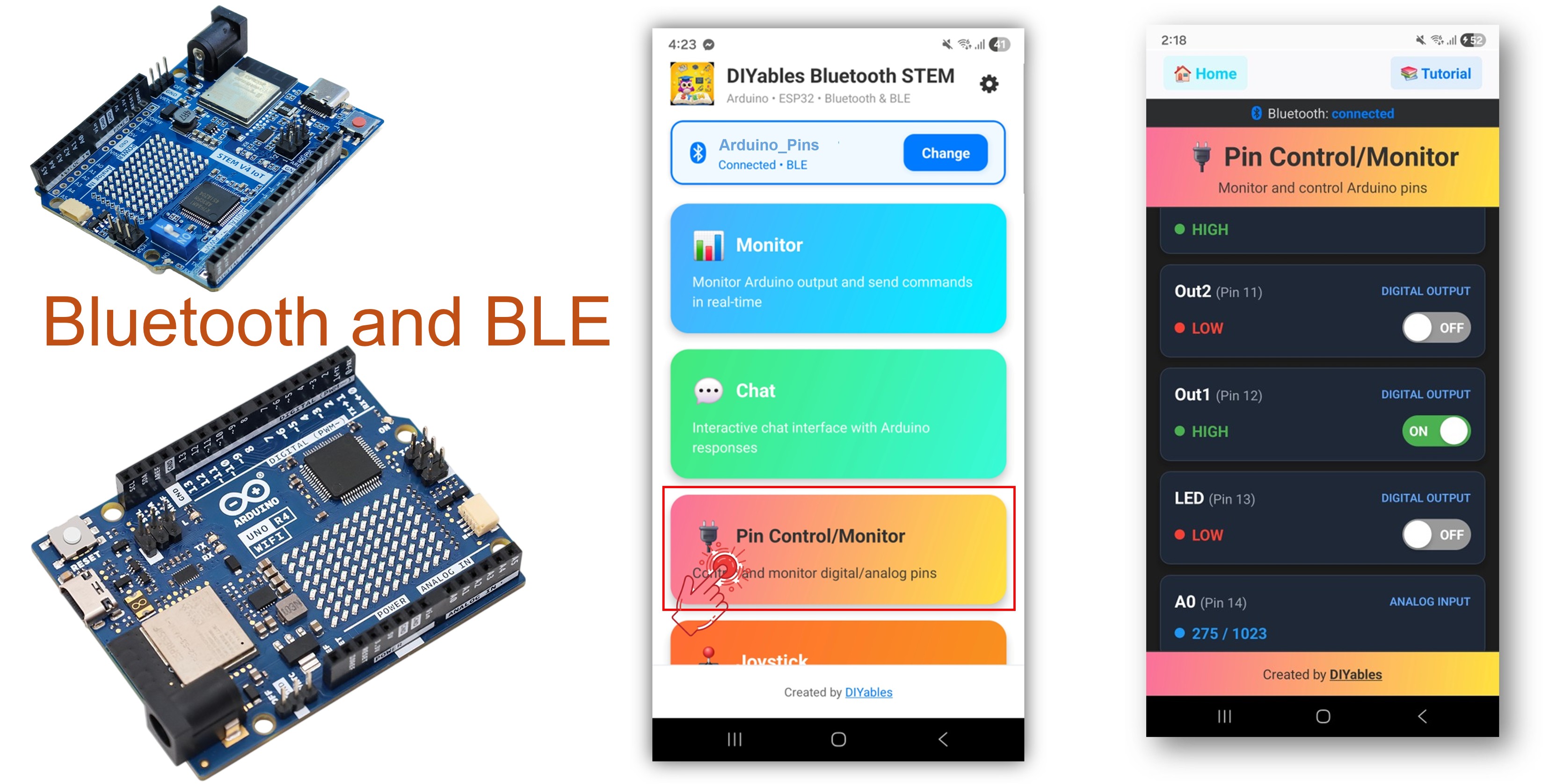
Das Bluetooth Digital Pins Beispiel bietet ferngesteuerte GPIO Pin-Kontrolle und -Überwachung, zugänglich über die DIYables Bluetooth STEM App. Entwickelt für Arduino UNO R4 WiFi mit BLE (Bluetooth Low Energy) zur drahtlosen Steuerung von Ausgangspins und Überwachung von Eingangspins über Ihr Smartphone. Perfekt für Relais-Steuerung, Button-Überwachung, LED-Schaltung und jede Anwendung, die Remote-Pin-Zugriff benötigt.

Hinweis: Der Arduino UNO R4 WiFi unterstützt nur BLE (Bluetooth Low Energy). Er unterstützt kein Classic Bluetooth. Die DIYables Bluetooth App unterstützt sowohl BLE als auch Classic Bluetooth auf Android und BLE auf iOS. Da diese Platine BLE verwendet, funktioniert die App auf sowohl Android als auch iOS.

Arduino UNO R4 WiFi Bluetooth Digital Pins Beispiel - GPIO Pin-Steuerung via BLE Tutorial

Funktionen

  • Ausgangssteuerung: Setzen Sie digitale Pins ferngesteuert auf HIGH/LOW
  • Eingangsüberwachung: Lesen Sie digitale und analoge Pin-Zustände
  • Benannte Pins: Weisen Sie jedem Pin benutzerfreundliche Namen zu (z.B. "LED", "Relay")
  • Echtzeit-Updates: Übertragen Sie Pin-Zustandsänderungen an die App
  • Bis zu 16 Pins: Steuern Sie mehrere Pins gleichzeitig
  • Funktioniert auf Android & iOS: BLE wird auf beiden Plattformen unterstützt
  • Keine Kopplung erforderlich: BLE verbindet sich automatisch ohne manuelle Kopplung

Hardware erforderlich

1×Arduino UNO R4 WiFi
1×Alternativ: DIYables STEM V4 IoT
1×USB-Kabel Typ-C
1×Breadboard
1×Jumper-Kabel
1×(Empfohlen) Schraubklemmenblock-Shield für Arduino Uno R4
1×(Empfohlen) Breadboard-Shield für Arduino Uno R4
1×(Empfohlen) Gehäuse für Arduino Uno R4
1×(Empfohlen) Stromverteiler für Arduino Uno R4
1×(Empfohlen) Prototyping-Grundplatte & Breadboard-Kit für Arduino Uno

Oder Sie können die folgenden Kits kaufen:

1×DIYables STEM V4 IoT Starter-Kit (Arduino enthalten)
1×DIYables Sensor-Kit (30 Sensoren/Displays)
1×DIYables Sensor-Kit (18 Sensoren/Displays)
Offenlegung: Einige der in diesem Abschnitt bereitgestellten Links sind Amazon-Affiliate-Links. Wir können eine Provision für Käufe erhalten, die über diese Links getätigt werden, ohne zusätzliche Kosten für Sie. Wir schätzen Ihre Unterstützung.

Arduino UNO R4 WiFi Code

Schnellstart-Schritte

Folgen Sie diesen Anweisungen Schritt für Schritt:

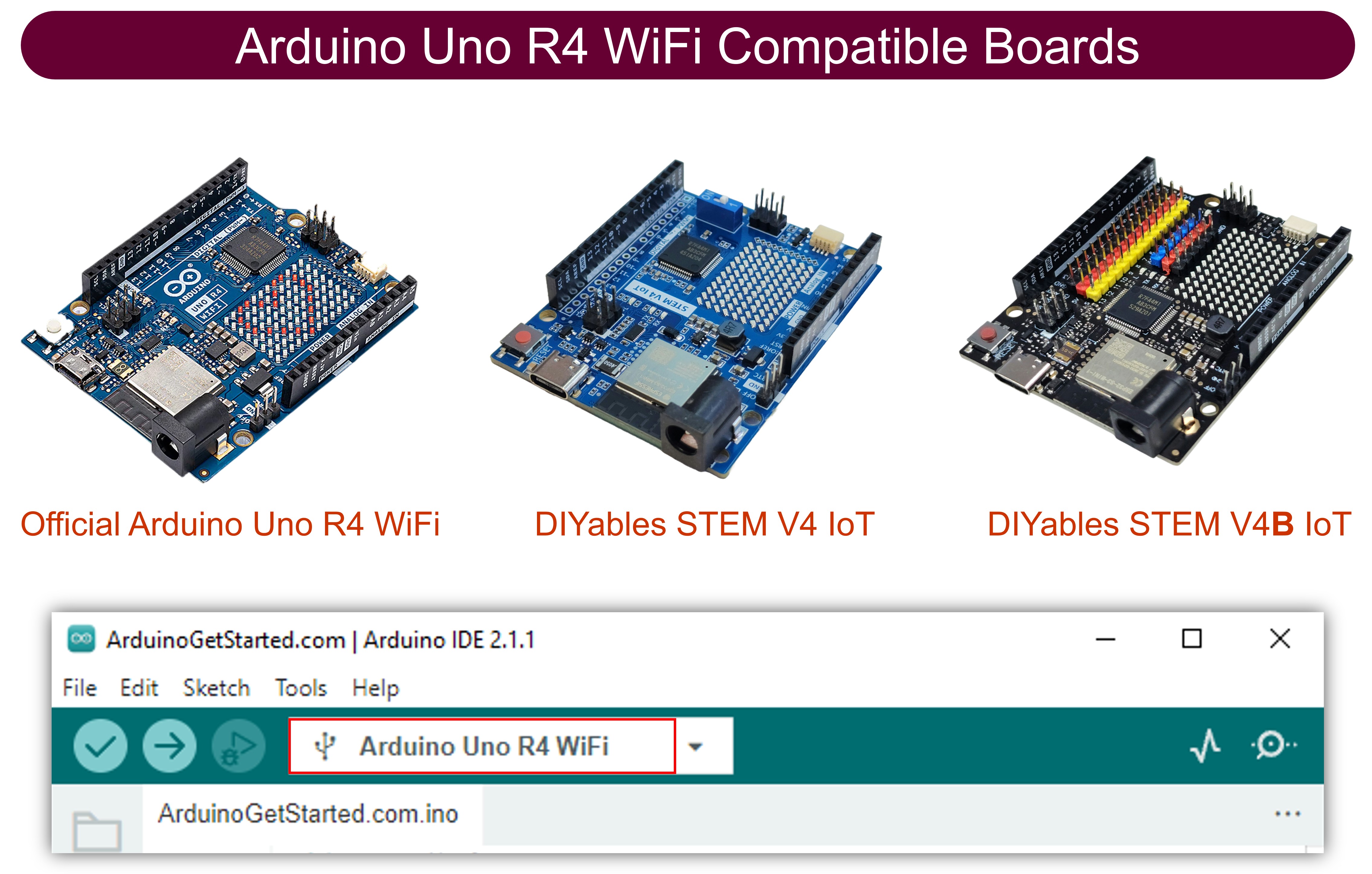
  • Falls Sie den Arduino UNO R4 WiFi zum ersten Mal verwenden, lesen Sie den Arduino UNO R4 WiFi Erste Schritte Leitfaden.
  • Verbinden Sie die Arduino UNO R4 WiFi Platine über ein USB-Kabel mit Ihrem Computer.
  • Starten Sie die Arduino IDE auf Ihrem Computer.
  • Wählen Sie Arduino UNO R4 WiFi Platine und den entsprechenden COM-Port.
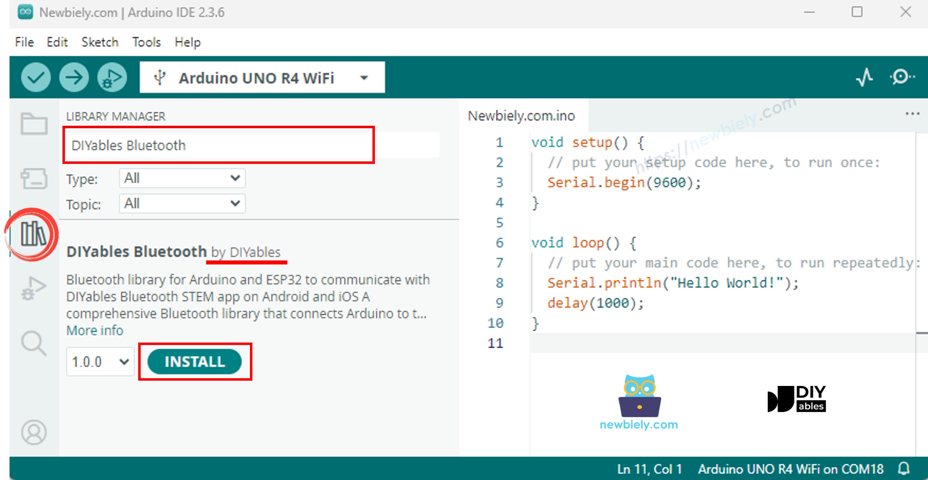
  • Navigieren Sie zum Libraries Symbol in der linken Leiste der Arduino IDE.
  • Suchen Sie nach "DIYables Bluetooth" und finden Sie die DIYables Bluetooth Bibliothek von DIYables
  • Klicken Sie auf Install um die Bibliothek zu installieren.
Arduino UNO R4 DIYables Bluetooth Bibliothek
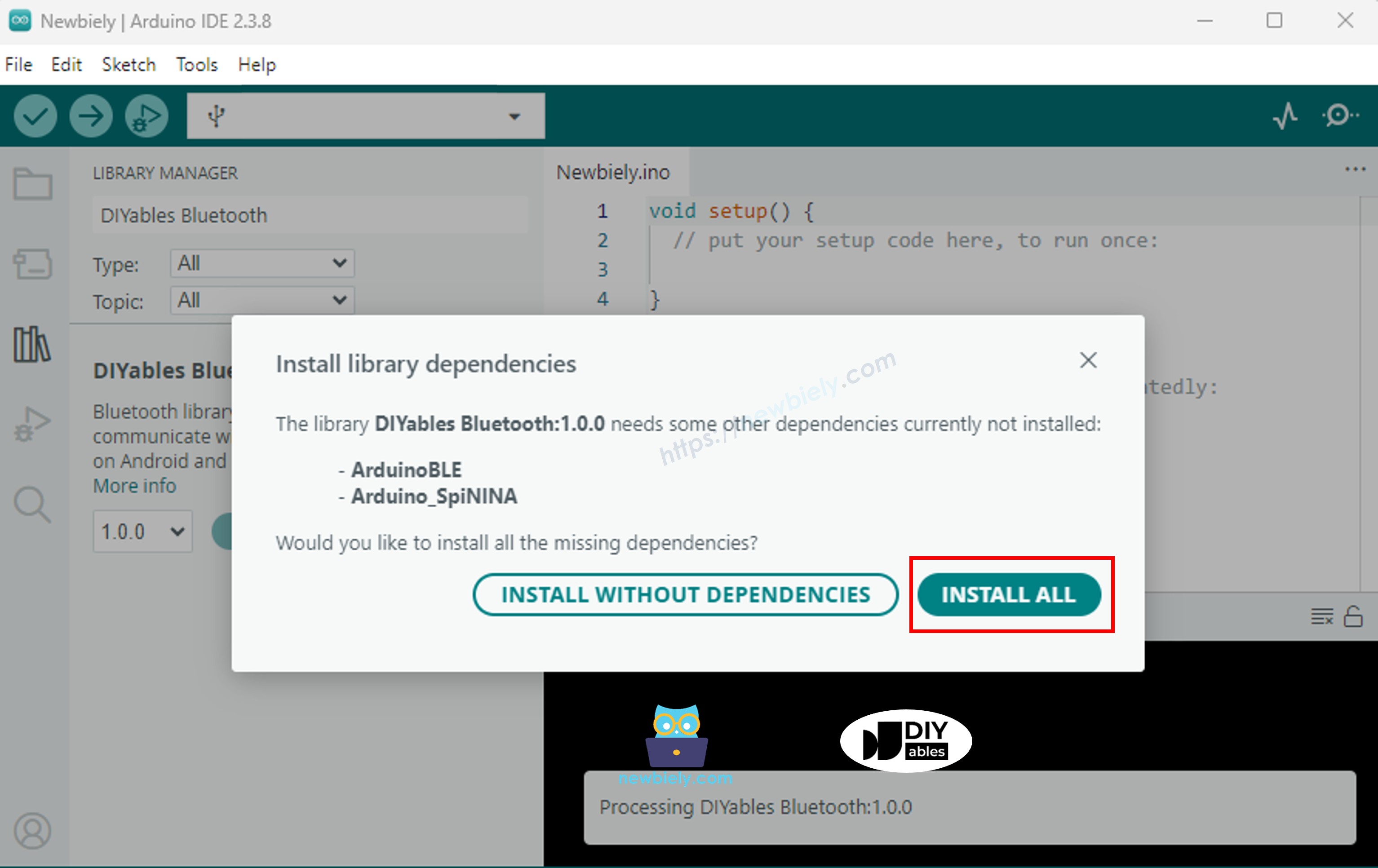
  • Sie werden nach der Installation einiger anderer Bibliotheksabhängigkeiten gefragt
  • Klicken Sie auf Install All um alle Bibliotheksabhängigkeiten zu installieren.
Arduino UNO R4 DIYables Bluetooth Abhängigkeit

BLE Code

  • Gehen Sie in der Arduino IDE zu File Examples DIYables Bluetooth ArduinoBLE_PinControl Beispiel, oder kopieren Sie den obigen Code und fügen Sie ihn in den Editor der Arduino IDE ein
/* * DIYables Bluetooth Library - Bluetooth Pin Control/Monitor Example * Works with DIYables Bluetooth STEM app on Android and iOS * * This example demonstrates the Bluetooth Pin Control/Monitor feature: * - Control digital output pins via Bluetooth * - Monitor digital input pins * - Monitor analog input pins * - Configure pin modes (INPUT/OUTPUT) * * Compatible Boards: * - Arduino UNO R4 WiFi * - Arduino Nano 33 BLE / BLE Sense * - Arduino Nano 33 IoT * - Arduino MKR WiFi 1010 * - Arduino Nano RP2040 Connect * - Any board supporting the ArduinoBLE library * * Setup: * 1. Upload the sketch to your Arduino * 2. Open Serial Monitor to see connection status * 3. Use DIYables Bluetooth App to connect and control pins * * Tutorial: https://diyables.io/bluetooth-app * Author: DIYables */ #include <DIYables_BluetoothServer.h> #include <DIYables_BluetoothPinControl.h> #include <platforms/DIYables_ArduinoBLE.h> // BLE Configuration const char* DEVICE_NAME = "Arduino_Pins"; const char* SERVICE_UUID = "19B10000-E8F2-537E-4F6C-D104768A1214"; const char* TX_UUID = "19B10001-E8F2-537E-4F6C-D104768A1214"; const char* RX_UUID = "19B10002-E8F2-537E-4F6C-D104768A1214"; // Create Bluetooth instances DIYables_ArduinoBLE bluetooth(DEVICE_NAME, SERVICE_UUID, TX_UUID, RX_UUID); DIYables_BluetoothServer bluetoothServer(bluetooth); // Create Pin Control/Monitor app instance DIYables_BluetoothPinControl bluetoothPins; // Pin configuration const int LED_PIN = 13; const int OUTPUT_PIN_1 = 12; const int OUTPUT_PIN_2 = 11; const int INPUT_PIN_1 = 7; const int INPUT_PIN_2 = 6; const int ANALOG_PIN_1 = A0; const int ANALOG_PIN_2 = A1; void setup() { Serial.begin(9600); while (!Serial); Serial.println("DIYables Bluetooth - Pin Control/Monitor Example"); // Initialize pins pinMode(LED_PIN, OUTPUT); pinMode(OUTPUT_PIN_1, OUTPUT); pinMode(OUTPUT_PIN_2, OUTPUT); pinMode(INPUT_PIN_1, INPUT_PULLUP); pinMode(INPUT_PIN_2, INPUT_PULLUP); // Initialize Bluetooth server with platform-specific implementation bluetoothServer.begin(); // Add digital pins app to server bluetoothServer.addApp(&bluetoothPins); // Configure which pins are accessible via Bluetooth with custom names bluetoothPins.enablePin(LED_PIN, BT_PIN_OUTPUT, "LED"); bluetoothPins.enablePin(OUTPUT_PIN_1, BT_PIN_OUTPUT, "Out1"); bluetoothPins.enablePin(OUTPUT_PIN_2, BT_PIN_OUTPUT, "Out2"); bluetoothPins.enablePin(INPUT_PIN_1, BT_PIN_INPUT, "Btn1"); bluetoothPins.enablePin(INPUT_PIN_2, BT_PIN_INPUT, "Btn2"); bluetoothPins.enablePin(ANALOG_PIN_1, BT_PIN_INPUT, "A0"); bluetoothPins.enablePin(ANALOG_PIN_2, BT_PIN_INPUT, "A1"); // Set up connection event callbacks bluetoothServer.setOnConnected([]() { Serial.println("Bluetooth connected!"); }); bluetoothServer.setOnDisconnected([]() { Serial.println("Bluetooth disconnected!"); }); // Set up callback for pin write commands bluetoothPins.onPinWrite([](int pin, int state) { digitalWrite(pin, state); Serial.print("Pin "); Serial.print(pin); Serial.print(" set to "); Serial.println(state ? "HIGH" : "LOW"); }); // Set up callback for pin read commands bluetoothPins.onPinRead([](int pin) -> int { // Read analog pins with analogRead, digital pins with digitalRead int state; if (pin == ANALOG_PIN_1 || pin == ANALOG_PIN_2) { state = analogRead(pin); Serial.print("Analog pin "); Serial.print(pin); Serial.print(" read: "); Serial.println(state); } else { state = digitalRead(pin); Serial.print("Digital pin "); Serial.print(pin); Serial.print(" read: "); Serial.println(state ? "HIGH" : "LOW"); } return state; }); // Set up callback for pin mode changes bluetoothPins.onPinModeChange([](int pin, int mode) { pinMode(pin, mode == BT_PIN_OUTPUT ? OUTPUT : INPUT_PULLUP); Serial.print("Pin "); Serial.print(pin); Serial.print(" mode changed to "); Serial.println(mode == BT_PIN_OUTPUT ? "OUTPUT" : "INPUT"); }); Serial.println("Waiting for Bluetooth connection..."); Serial.print("Enabled pins: "); Serial.println(bluetoothPins.getEnabledPinCount()); } void loop() { // Handle Bluetooth server communications bluetoothServer.loop(); // Optional: Monitor input pins and send updates static unsigned long lastInputCheck = 0; static int lastInputState1 = HIGH; static int lastInputState2 = HIGH; static int lastAnalogState1 = 0; static int lastAnalogState2 = 0; if (millis() - lastInputCheck >= 100) { lastInputCheck = millis(); // Check digital input pin 1 int currentState1 = digitalRead(INPUT_PIN_1); if (currentState1 != lastInputState1) { lastInputState1 = currentState1; bluetoothPins.updatePinState(INPUT_PIN_1, currentState1); Serial.print("Input pin "); Serial.print(INPUT_PIN_1); Serial.print(" changed to "); Serial.println(currentState1 ? "HIGH" : "LOW"); } // Check digital input pin 2 int currentState2 = digitalRead(INPUT_PIN_2); if (currentState2 != lastInputState2) { lastInputState2 = currentState2; bluetoothPins.updatePinState(INPUT_PIN_2, currentState2); Serial.print("Input pin "); Serial.print(INPUT_PIN_2); Serial.print(" changed to "); Serial.println(currentState2 ? "HIGH" : "LOW"); } // Check analog input 1 (send update if changed by more than 10) int currentAnalog1 = analogRead(ANALOG_PIN_1); if (abs(currentAnalog1 - lastAnalogState1) > 10) { lastAnalogState1 = currentAnalog1; bluetoothPins.updatePinState(ANALOG_PIN_1, currentAnalog1); Serial.print("Analog pin "); Serial.print(ANALOG_PIN_1); Serial.print(" changed to "); Serial.println(currentAnalog1); } // Check analog input 2 (send update if changed by more than 10) int currentAnalog2 = analogRead(ANALOG_PIN_2); if (abs(currentAnalog2 - lastAnalogState2) > 10) { lastAnalogState2 = currentAnalog2; bluetoothPins.updatePinState(ANALOG_PIN_2, currentAnalog2); Serial.print("Analog pin "); Serial.print(ANALOG_PIN_2); Serial.print(" changed to "); Serial.println(currentAnalog2); } } delay(10); }
  • Klicken Sie auf Upload in der Arduino IDE, um den Code auf den Arduino UNO R4 WiFi hochzuladen
  • Öffnen Sie den Serial Monitor
  • Überprüfen Sie das Ergebnis im Serial Monitor. Es sieht folgendermaßen aus:
COM6
Send
DIYables Bluetooth - Pin Control/Monitor Example Waiting for Bluetooth connection... Enabled pins: 7
Autoscroll Show timestamp
Clear output
9600 baud  
Newline  

Mobile App

  • Installieren Sie die DIYables Bluetooth App auf Ihrem Smartphone: Android | iOS

Hinweis: Die DIYables Bluetooth App unterstützt sowohl BLE als auch Classic Bluetooth auf Android und BLE auf iOS. Da der Arduino UNO R4 WiFi BLE verwendet, funktioniert die App auf sowohl Android als auch iOS. Für BLE ist keine manuelle Kopplung erforderlich — scannen und verbinden Sie sich einfach.

  • Öffnen Sie die DIYables Bluetooth App
  • Bei der ersten Verwendung der App werden Sie um Berechtigungen gebeten. Gewähren Sie bitte folgende:
    • Nearby Devices Berechtigung (Android 12+) / Bluetooth Berechtigung (iOS) - erforderlich zum Scannen und Verbinden mit Bluetooth-Geräten
    • Location Berechtigung (nur Android 11 und früher) - von älteren Android-Versionen zum Scannen nach BLE-Geräten benötigt
  • Stellen Sie sicher, dass Bluetooth auf Ihrem Telefon eingeschaltet ist
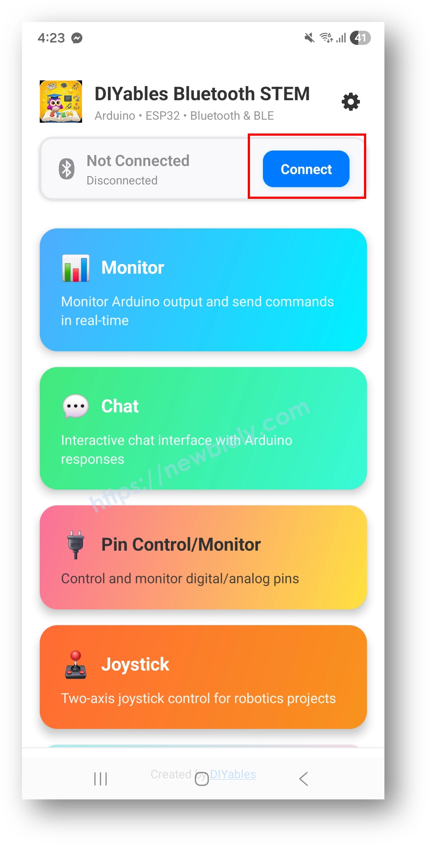
  • Tippen Sie auf dem Startbildschirm auf Connect. Die App scannt nach BLE-Geräten.
DIYables Bluetooth App - Startbildschirm mit Scan Button
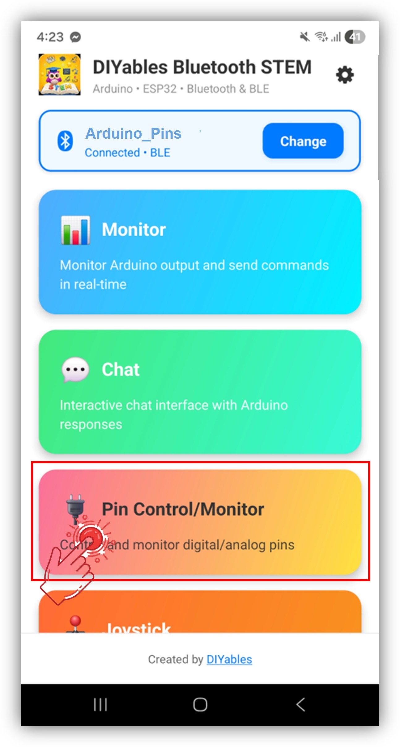
  • Finden und tippen Sie auf "Arduino_Pins" in den Scan-Ergebnissen, um sich zu verbinden.
  • Nach der Verbindung kehrt die App automatisch zum Startbildschirm zurück. Wählen Sie die Digital Pins App aus dem App-Menü.
DIYables Bluetooth App - Startbildschirm mit Digital Pins App

Hinweis: Sie können auf das Einstellungs-Symbol auf dem Startbildschirm tippen, um Apps auf dem Startbildschirm ein-/auszublenden. Für weitere Details siehe das DIYables Bluetooth App Benutzerhandbuch.

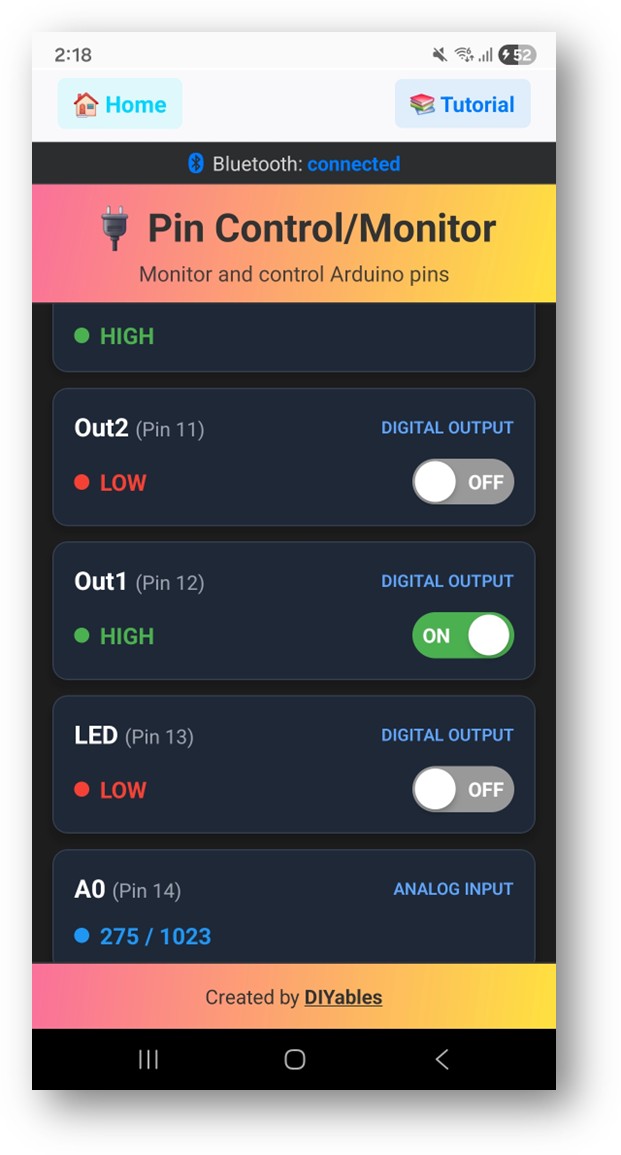
  • Sie sehen die Liste der aktivierten Pins mit ihren Namen und aktuellen Zuständen
  • Tippen Sie auf Ausgangspins, um HIGH/LOW zu wechseln, und beobachten Sie die Aktualisierung der Eingangspin-Werte
DIYables Bluetooth App - Digital Pins Bildschirm

Schauen Sie nun zurück zum Serial Monitor in der Arduino IDE. Sie werden sehen:

COM6
Send
Bluetooth connected! Pin 13 set to HIGH Pin 13 set to LOW Digital pin 7 read: HIGH
Autoscroll Show timestamp
Clear output
9600 baud  
Newline  

Kreative Anpassung - Code an Ihr Projekt anpassen

Pins aktivieren

// Enable pins with mode and friendly name bluetoothPins.enablePin(13, BT_PIN_OUTPUT, "LED"); bluetoothPins.enablePin(12, BT_PIN_OUTPUT, "Relay"); bluetoothPins.enablePin(7, BT_PIN_INPUT, "Button"); bluetoothPins.enablePin(A0, BT_PIN_INPUT, "Sensor"); // Check enabled pin count int count = bluetoothPins.getEnabledPinCount();

Pin Write/Read/Mode behandeln

bluetoothPins.onPinWrite([](int pin, int state) { digitalWrite(pin, state); Serial.print("Pin "); Serial.print(pin); Serial.println(state ? " ? HIGH" : " ? LOW"); }); bluetoothPins.onPinRead([](int pin) -> int { if (pin >= A0) { return analogRead(pin); } return digitalRead(pin); }); bluetoothPins.onPinModeChange([](int pin, int mode) { pinMode(pin, mode == BT_PIN_OUTPUT ? OUTPUT : INPUT_PULLUP); });

Zustandsänderungen übertragen

// Notify the app when a pin state changes bluetoothPins.updatePinState(7, digitalRead(7)); bluetoothPins.updatePinState(A0, analogRead(A0));

Programmierbeispiele

Relais-Steuerung mit Button-Überwachung

const int RELAY_PIN = 12; const int BUTTON_PIN = 7; void setup() { pinMode(RELAY_PIN, OUTPUT); pinMode(BUTTON_PIN, INPUT_PULLUP); bluetoothPins.enablePin(RELAY_PIN, BT_PIN_OUTPUT, "Relay"); bluetoothPins.enablePin(BUTTON_PIN, BT_PIN_INPUT, "Button"); bluetoothPins.onPinWrite([](int pin, int state) { digitalWrite(pin, state); }); } void loop() { bluetoothServer.loop(); // Monitor button and push changes static int lastState = HIGH; int state = digitalRead(BUTTON_PIN); if (state != lastState) { lastState = state; bluetoothPins.updatePinState(BUTTON_PIN, state); } delay(10); }

Multi-LED Controller

const int LED_PINS[] = {8, 9, 10, 11, 12, 13}; const char* LED_NAMES[] = {"Red", "Green", "Blue", "Yellow", "White", "Built-in"}; const int NUM_LEDS = 6; void setup() { for (int i = 0; i < NUM_LEDS; i++) { pinMode(LED_PINS[i], OUTPUT); bluetoothPins.enablePin(LED_PINS[i], BT_PIN_OUTPUT, LED_NAMES[i]); } bluetoothPins.onPinWrite([](int pin, int state) { digitalWrite(pin, state); }); }

Fehlerbehebung

Häufige Probleme

1. Gerät kann in der App nicht gefunden werden

  • Stellen Sie sicher, dass der Arduino UNO R4 WiFi eingeschaltet ist und der Sketch hochgeladen wurde
  • Stellen Sie sicher, dass Bluetooth auf Ihrem Telefon aktiviert ist
  • Auf Android 11 und früher aktivieren Sie auch die Standortdienste

2. Pin-Umschaltung funktioniert nicht

  • Überprüfen Sie, ob der Pin mit BT_PIN_OUTPUT Modus aktiviert ist
  • Prüfen Sie, ob der onPinWrite Callback eingerichtet ist
  • Überprüfen Sie die Verkabelung

3. Eingangspins werden nicht aktualisiert

  • Stellen Sie sicher, dass updatePinState() aufgerufen wird, wenn sich der Pin-Zustand ändert
  • Überprüfen Sie die Polling-Frequenz in der Schleife

4. Analogwerte werden nicht angezeigt

  • Verwenden Sie analogRead() im onPinRead Callback für analoge Pins
  • Analoge Pins geben Werte von 0-1023 zurück

5. Verbindung bricht häufig ab

  • Gehen Sie näher zum Arduino (reduzieren Sie die Entfernung)
  • Stellen Sie eine stabile USB-Stromversorgung sicher

6. Upload schlägt fehl oder Platine wird nicht erkannt

  • Installieren Sie das neueste Arduino UNO R4 Board-Paket über den Board Manager
  • Versuchen Sie ein anderes USB-Kabel oder einen anderen Port

Projektideen

  • Multi-Relais-Steuerungsfeld
  • Button- und Schalter-Monitor
  • LED-Beleuchtungssteuerung
  • Heimautomatisierungs-Schaltfeld
  • Sensoreingabe-Dashboard

Nächste Schritte

Nach der Beherrschung des Bluetooth Digital Pins Beispiels, probieren Sie:

  1. Bluetooth Slider - Für analoge Wertsteuerung
  2. Bluetooth Monitor - Für textbasiertes Status-Feedback
  3. Bluetooth Table - Für strukturierte Pin-Status-Anzeige
  4. Mehrere Bluetooth Apps - Kombination von Pin-Steuerung mit anderen Apps

Support

Für zusätzliche Hilfe:

  • Überprüfen Sie die API-Referenzdokumentation
  • Besuchen Sie DIYables Tutorials
  • Arduino Community-Foren

※ UNSERE NACHRICHTEN

  • Sie können gerne den Link zu diesem Tutorial teilen. Bitte verwenden Sie jedoch unsere Inhalte nicht auf anderen Websites. Wir haben viel Mühe und Zeit in die Erstellung der Inhalte investiert, bitte respektieren Sie unsere Arbeit!