Arduino Nano ESP32 Bluetooth Digital Pins Beispiel - GPIO Pin Steuerung über BLE Tutorial
Übersicht
Dieses Beispiel bietet Remote-GPIO-Pin-Steuerung und -Überwachung auf dem Arduino Nano ESP32 mit BLE (Bluetooth Low Energy) über die DIYables Bluetooth STEM App. Steuern Sie Ausgabe-Pins und überwachen Sie Eingabe-Pins drahtlos von einem Smartphone aus. Geeignet für Relaissteuerung, Button-Überwachung, LED-Schalter und alle Anwendungen, die Remote-Pin-Zugriff erfordern.
Hinweis: Der Arduino Nano ESP32 unterstützt nur BLE – Classic Bluetooth wird nicht unterstützt. Die DIYables Bluetooth App funktioniert auf Android und iOS mit BLE.
Funktionen
Ausgabesteuerung: Digitale Pins remote auf HIGH oder LOW setzen
Eingabeüberwachung: Lesen Sie den Status digitaler und analoger Pins
Benannte Pins: Weisen Sie jedem Pin einen beschreibenden Namen zu (z. B. "LED", "Relais")
Echtzeit-Updates: Push-Pin-Status-Änderungen an die App
Bis zu 16 Pins: Steuern Sie mehrere Pins gleichzeitig
Android & iOS Unterstützung: BLE ist auf beiden Plattformen kompatibel
Keine Kopplung erforderlich: BLE verbindet sich ohne manuelle Kopplung
Offenlegung: Einige der in diesem Abschnitt bereitgestellten Links sind Amazon-Affiliate-Links. Wir können eine Provision für Käufe erhalten, die über diese Links getätigt werden, ohne zusätzliche Kosten für Sie. Wir schätzen Ihre Unterstützung.
Verbinden Sie den Arduino Nano ESP32 über USB mit Ihrem Computer.
Öffnen Sie Arduino IDE.
Wählen Sie das Arduino Nano ESP32 Board und den korrekten COM-Port.
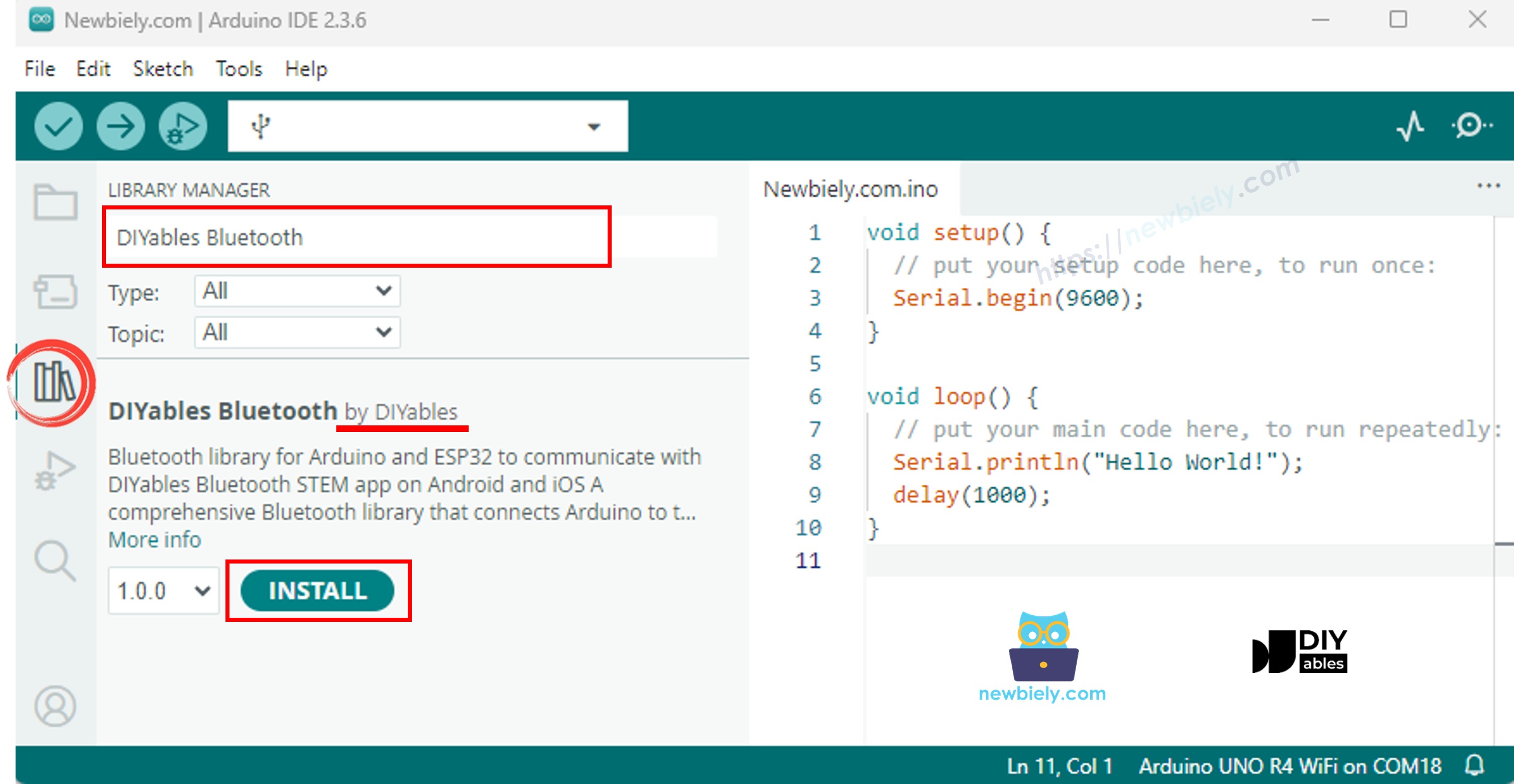
Klicken Sie auf das Libraries Symbol in der linken Seitenleiste.
Suchen Sie nach "DIYables Bluetooth" und wählen Sie die DIYables Bluetooth Bibliothek von DIYables.
Klicken Sie auf Install.
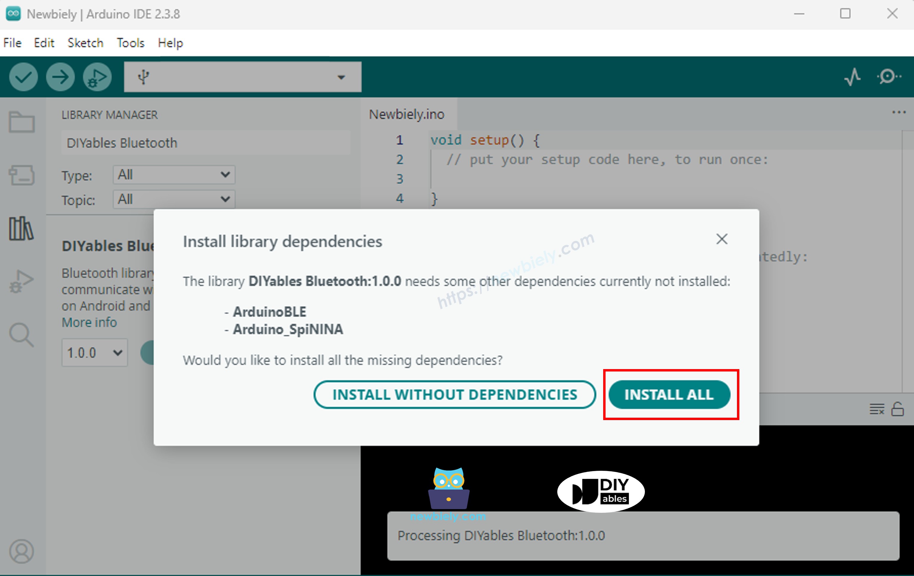
Wenn Sie aufgefordert werden, Abhängigkeiten zu installieren, klicken Sie auf Alles installieren.
BLE Code
In Arduino IDE, öffnen Sie File Examples DIYables Bluetooth ArduinoBLE_PinControl, oder fügen Sie den Code in den Editor ein.
/* * DIYables Bluetooth Library - ESP32 BLE Pin Control/Monitor Example * Works with DIYables Bluetooth STEM app on Android and iOS * * This example demonstrates the Bluetooth Pin Control/Monitor feature: * - Control digital output pins via Bluetooth * - Monitor digital input pins * - Monitor analog input pins * - Configure pin modes (INPUT/OUTPUT) * * Tutorial: https://diyables.io/bluetooth-app * Author: DIYables */#include <DIYables_BluetoothServer.h>#include <DIYables_BluetoothPinControl.h>#include <platforms/DIYables_Esp32BLE.h>// BLE Configurationconst char* DEVICE_NAME = "ESP32BLE_Pins";const char* SERVICE_UUID = "19B10000-E8F2-537E-4F6C-D104768A1214";const char* TX_UUID = "19B10001-E8F2-537E-4F6C-D104768A1214";const char* RX_UUID = "19B10002-E8F2-537E-4F6C-D104768A1214";// Create Bluetooth instancesDIYables_Esp32BLE bluetooth(DEVICE_NAME, SERVICE_UUID, TX_UUID, RX_UUID);DIYables_BluetoothServer bluetoothServer(bluetooth);// Create Pin Control/Monitor app instanceDIYables_BluetoothPinControl bluetoothPins;// Pin configuration (ESP32 GPIOs)constint LED_PIN = LED_BUILTIN; // Built-in LEDconstint OUTPUT_PIN_1 = D6;constint OUTPUT_PIN_2 = D7;constint INPUT_PIN_1 = D4;constint INPUT_PIN_2 = D5;constint ANALOG_PIN_1 = A0; // Input-only ADC pinconstint ANALOG_PIN_2 = A1; // Input-only ADC pinvoidsetup() {Serial.begin(115200);delay(1000);Serial.println("DIYables Bluetooth - ESP32 BLE Pin Control/Monitor Example");// Initialize pinspinMode(LED_PIN, OUTPUT);pinMode(OUTPUT_PIN_1, OUTPUT);pinMode(OUTPUT_PIN_2, OUTPUT);pinMode(INPUT_PIN_1, INPUT_PULLUP);pinMode(INPUT_PIN_2, INPUT_PULLUP);// Initialize Bluetooth server with platform-specific implementation bluetoothServer.begin();// Add digital pins app to server bluetoothServer.addApp(&bluetoothPins);// Configure which pins are accessible via Bluetooth with custom names bluetoothPins.enablePin(LED_PIN, BT_PIN_OUTPUT, "LED"); bluetoothPins.enablePin(OUTPUT_PIN_1, BT_PIN_OUTPUT, "Out1"); bluetoothPins.enablePin(OUTPUT_PIN_2, BT_PIN_OUTPUT, "Out2"); bluetoothPins.enablePin(INPUT_PIN_1, BT_PIN_INPUT, "Btn1"); bluetoothPins.enablePin(INPUT_PIN_2, BT_PIN_INPUT, "Btn2"); bluetoothPins.enablePin(ANALOG_PIN_1, BT_PIN_INPUT, "A34"); bluetoothPins.enablePin(ANALOG_PIN_2, BT_PIN_INPUT, "A35");// Set up connection event callbacks bluetoothServer.setOnConnected([]() {Serial.println("Bluetooth connected!"); }); bluetoothServer.setOnDisconnected([]() {Serial.println("Bluetooth disconnected!"); });// Set up callback for pin write commands bluetoothPins.onPinWrite([](int pin, int state) {digitalWrite(pin, state);Serial.print("Pin ");Serial.print(pin);Serial.print(" set to ");Serial.println(state ? "HIGH" : "LOW"); });// Set up callback for pin read commands bluetoothPins.onPinRead([](int pin) -> int {int state;if (pin == ANALOG_PIN_1 || pin == ANALOG_PIN_2) { state = analogRead(pin);Serial.print("Analog pin ");Serial.print(pin);Serial.print(" read: ");Serial.println(state); } else { state = digitalRead(pin);Serial.print("Digital pin ");Serial.print(pin);Serial.print(" read: ");Serial.println(state ? "HIGH" : "LOW"); }return state; });// Set up callback for pin mode changes bluetoothPins.onPinModeChange([](int pin, int mode) {pinMode(pin, mode == BT_PIN_OUTPUT ? OUTPUT : INPUT_PULLUP);Serial.print("Pin ");Serial.print(pin);Serial.print(" mode changed to ");Serial.println(mode == BT_PIN_OUTPUT ? "OUTPUT" : "INPUT"); });Serial.println("Waiting for Bluetooth connection...");Serial.print("Enabled pins: ");Serial.println(bluetoothPins.getEnabledPinCount());}voidloop() { bluetoothServer.loop();staticunsignedlong lastInputCheck = 0;staticint lastInputState1 = HIGH;staticint lastInputState2 = HIGH;staticint lastAnalogState1 = 0;staticint lastAnalogState2 = 0;if (millis() - lastInputCheck >= 100) { lastInputCheck = millis();int currentState1 = digitalRead(INPUT_PIN_1);if (currentState1 != lastInputState1) { lastInputState1 = currentState1; bluetoothPins.updatePinState(INPUT_PIN_1, currentState1);Serial.print("Input pin ");Serial.print(INPUT_PIN_1);Serial.print(" changed to ");Serial.println(currentState1 ? "HIGH" : "LOW"); }int currentState2 = digitalRead(INPUT_PIN_2);if (currentState2 != lastInputState2) { lastInputState2 = currentState2; bluetoothPins.updatePinState(INPUT_PIN_2, currentState2);Serial.print("Input pin ");Serial.print(INPUT_PIN_2);Serial.print(" changed to ");Serial.println(currentState2 ? "HIGH" : "LOW"); }// ESP32 has 12-bit ADC (0-4095)int currentAnalog1 = analogRead(ANALOG_PIN_1);if (abs(currentAnalog1 - lastAnalogState1) > 40) { // ~1% of 4095 lastAnalogState1 = currentAnalog1; bluetoothPins.updatePinState(ANALOG_PIN_1, currentAnalog1);Serial.print("Analog pin ");Serial.print(ANALOG_PIN_1);Serial.print(" changed to ");Serial.println(currentAnalog1); }int currentAnalog2 = analogRead(ANALOG_PIN_2);if (abs(currentAnalog2 - lastAnalogState2) > 40) { lastAnalogState2 = currentAnalog2; bluetoothPins.updatePinState(ANALOG_PIN_2, currentAnalog2);Serial.print("Analog pin ");Serial.print(ANALOG_PIN_2);Serial.print(" changed to ");Serial.println(currentAnalog2); } }delay(10);}
Klicken Sie auf Upload, um den Sketch auf das Board zu flashen.
Öffnen Sie den Serial Monitor.
Die Serial Monitor Ausgabe sollte so aussehen:
Newbiely | Arduino IDE 2.3.8
──
☐
✕
File
Edit
Sketch
Tools
Help
Arduino Nano ESP32
Newbiely.ino
···
8Serial.println("Hello World!");
Output
Serial Monitor
Message (Enter to send message to 'Arduino Nano ESP32' on 'COM15')
New Line
9600 baud
DIYables Bluetooth - Pin Control/Monitor Example
Waiting for Bluetooth connection...
Enabled pins: 7
Ln 11, Col 1
Arduino Nano ESP32 on COM15
2
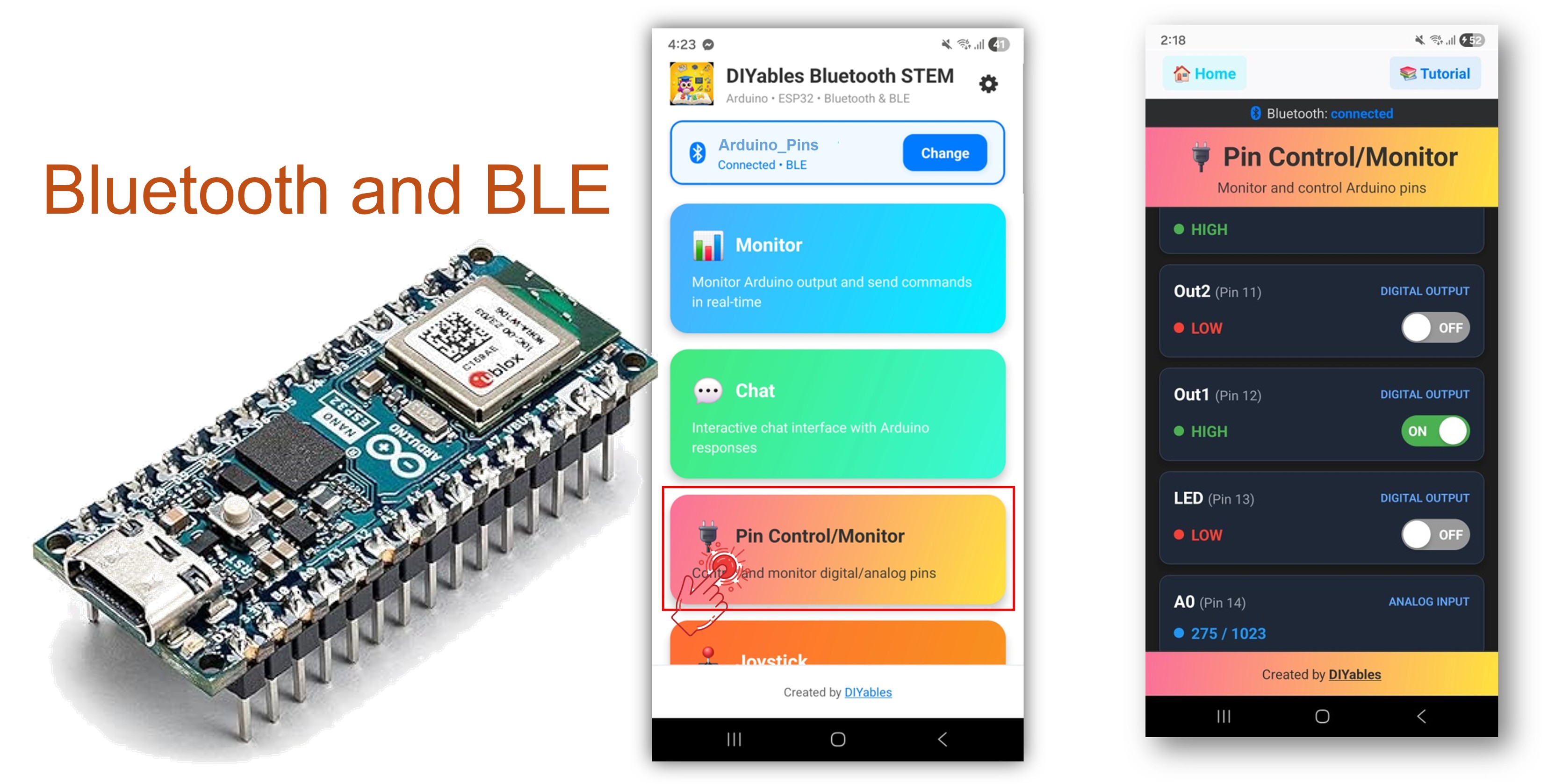
Mobile App
Installieren Sie die DIYables Bluetooth App auf Ihrem Smartphone: Android | iOS
Hinweis: Die DIYables Bluetooth App funktioniert auf Android und iOS mit BLE. Keine manuelle Kopplung erforderlich.
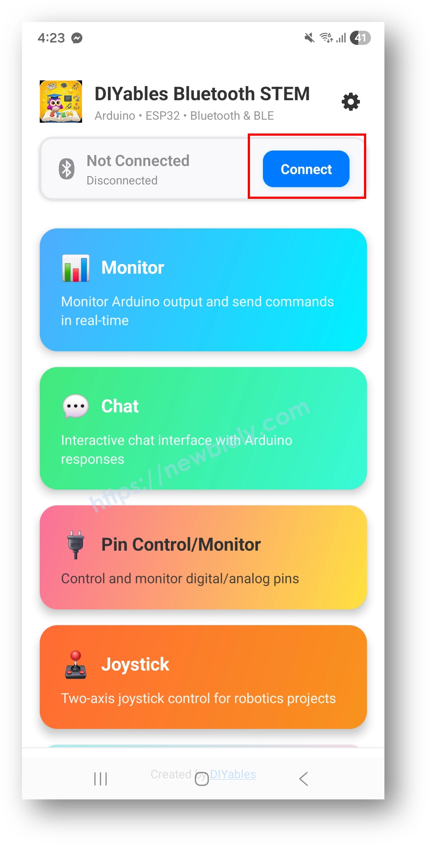
Starten Sie die DIYables Bluetooth App.
Beim ersten Start erteilen Sie folgende Berechtigungen:
Nahegelegene Geräte (Android 12+) / Bluetooth (iOS) – erforderlich zum Scannen und Verbinden mit Bluetooth-Geräten
Standort (nur Android 11 und älter) – erforderlich von älteren Android-Versionen zum Scannen nach BLE
Stellen Sie sicher, dass Bluetooth auf Ihrem Gerät aktiviert ist.
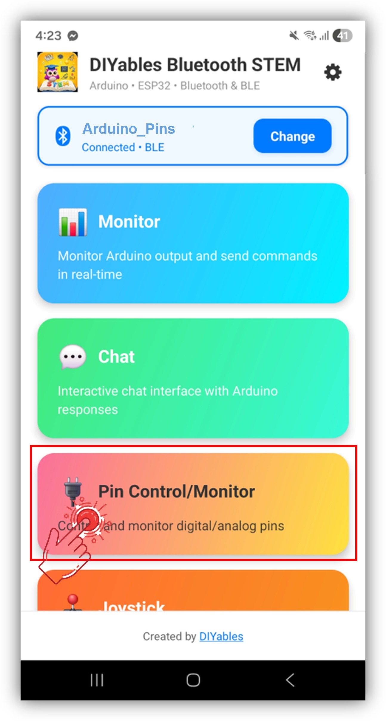
Tippen Sie auf Connect auf der Startseite. Die App scannt nach BLE-Geräten.
Tippen Sie auf "Arduino_Pins" in den Scan-Ergebnissen.
Nach der Verbindung kehren Sie zur Startseite zurück und öffnen Sie die Digital Pins App.
Tippen Sie auf das Einstellungssymbol auf der Startseite, um Apps anzuzeigen oder auszublenden. Weitere Informationen finden Sie im DIYables Bluetooth App Benutzerhandbuch.
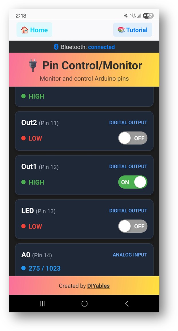
Die aktivierten Pins werden mit ihren Namen und aktuellen Status aufgelistet.
Tippen Sie auf Ausgabe-Pins, um HIGH/LOW umzuschalten, und beobachten Sie, wie sich die Eingabe-Pin-Werte in Echtzeit aktualisieren.
Schauen Sie jetzt im Serial Monitor der Arduino IDE nach. Sie werden sehen:
Newbiely | Arduino IDE 2.3.8
──
☐
✕
File
Edit
Sketch
Tools
Help
Arduino Nano ESP32
Newbiely.ino
···
8Serial.println("Hello World!");
Output
Serial Monitor
Message (Enter to send message to 'Arduino Nano ESP32' on 'COM15')
New Line
9600 baud
Bluetooth connected!
Pin 13 set to HIGH
Pin 13 set to LOW
Digital pin 7 read: HIGH
Ln 11, Col 1
Arduino Nano ESP32 on COM15
2
Kreative Anpassung - Passen Sie den Code an Ihr Projekt an
Sie können gerne den Link zu diesem Tutorial teilen. Bitte verwenden Sie jedoch unsere Inhalte nicht auf anderen Websites. Wir haben viel Mühe und Zeit in die Erstellung der Inhalte investiert, bitte respektieren Sie unsere Arbeit!