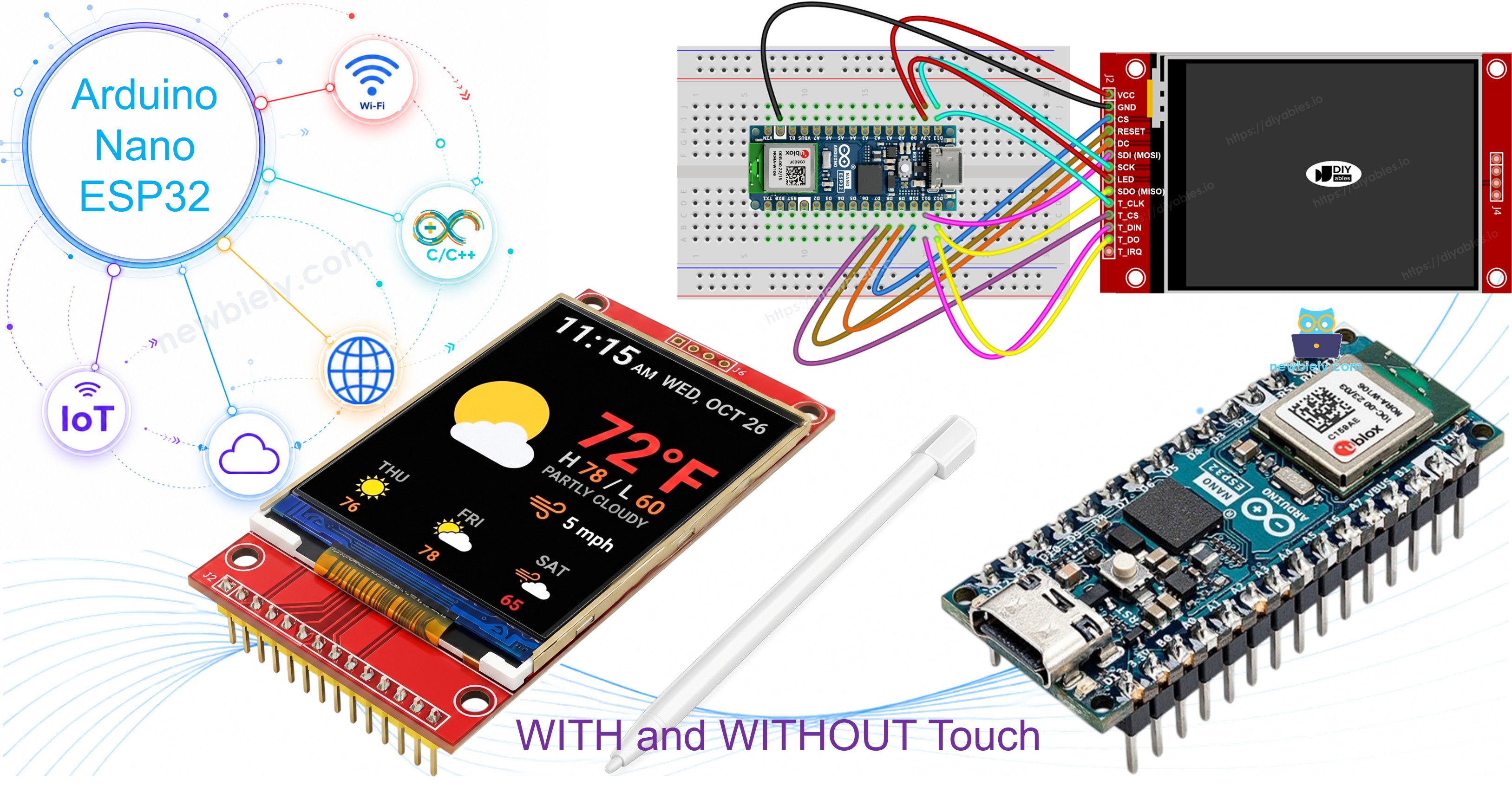
Arduino Nano ESP32 - ILI9341 ILI9488 ST7789 TFT LCD Touch Display SPI Interface
Willkommen zu diesem praktischen Workshop, in dem wir ein SPI TFT Display mit einem Arduino Nano ESP32 verbinden. Der Nano ESP32 basiert auf dem ESP32-S3 Chip und bietet Dual-Core-Verarbeitung, Wi-Fi und Bluetooth Low Energy in der vertrauten Nano-Form mit USB-C-Anschluss. Er arbeitet mit 3,3V, was der Spannungsstufe der meisten SPI TFT Module entspricht, was die Verdrahtung einfach macht.
In diesem Workshop werden Sie:
- Ein 3,3V SPI TFT Display mit dem Arduino Nano ESP32 verbinden.
- Formen und Grafiken mit Adafruit GFX Funktionen zeichnen.
- Text-Zeichenketten und Zahlen in verschiedenen Größen anzeigen.
- Bitmap-Bilder aus dem Programmspeicher (PROGMEM) zeichnen.
- Bitmap-Bilder von einer SD-Karte laden.
- Text mit einer benutzerdefinierten externen Schriftart rendern.
- Rohe Touch-Koordinaten von einem XPT2046 Touch-Controller lesen.
- Auf dem Bildschirm zeichnen durch Touch-Gesten.
- Interaktive Touch-Buttons erstellen.
- Den Touch-Bildschirm kalibrieren.
- Einen sekundären oder benutzerdefinierten SPI-Bus für das Display verwenden.
Dieser Workshop behandelt sowohl Touch- als auch Nicht-Touch SPI TFT LCD Displays. Er funktioniert mit 1,3, 1,54, 2,2, 2,4, 2,8, 3,2 und 3,5 Zoll Panels, die von ILI9341, ILI9488 oder ST7789 Controller-Chips angetrieben werden.
Benötigte Hardware
Oder Sie können die folgenden Kits kaufen:
| 1 | × | DIYables Sensor-Kit (18 Sensoren/Displays) |
Über das SPI TFT Display
SPI TFT Module verwenden einen Treiber-IC, um Pixeldaten zu verwalten und auf Zeichnungsbefehle über einen hochfrequenten SPI-Link zu reagieren. Drei Treiber werden unterstützt:
- ILI9341 - 16-Bit RGB565 Farbe, bis zu 40 MHz SPI.
- ILI9488 - 18-Bit RGB666 Farbe über SPI, bis zu 24 MHz.
- ST7789 - 16-Bit RGB565 Farbe, bis zu 40 MHz SPI.
Empfehlung: Wenn Sie noch kein Display gekauft haben, empfehlen wir den ST7789 Treiber. Er ist weit verbreitet, läuft mit voller 40-MHz-SPI-Geschwindigkeit und ist die einfachste Wahl für neue Projekte.
Die Bibliothek basiert auf Adafruit GFX, daher sind Kreise, Rechtecke, Text, benutzerdefinierte Schriftarten und Bitmaps alle sofort einsatzbereit.
Hinweis: Der Arduino Nano ESP32 verwendet 3,3V Logik. Verbinden Sie TFT VCC nur mit dem 3,3V Pin.
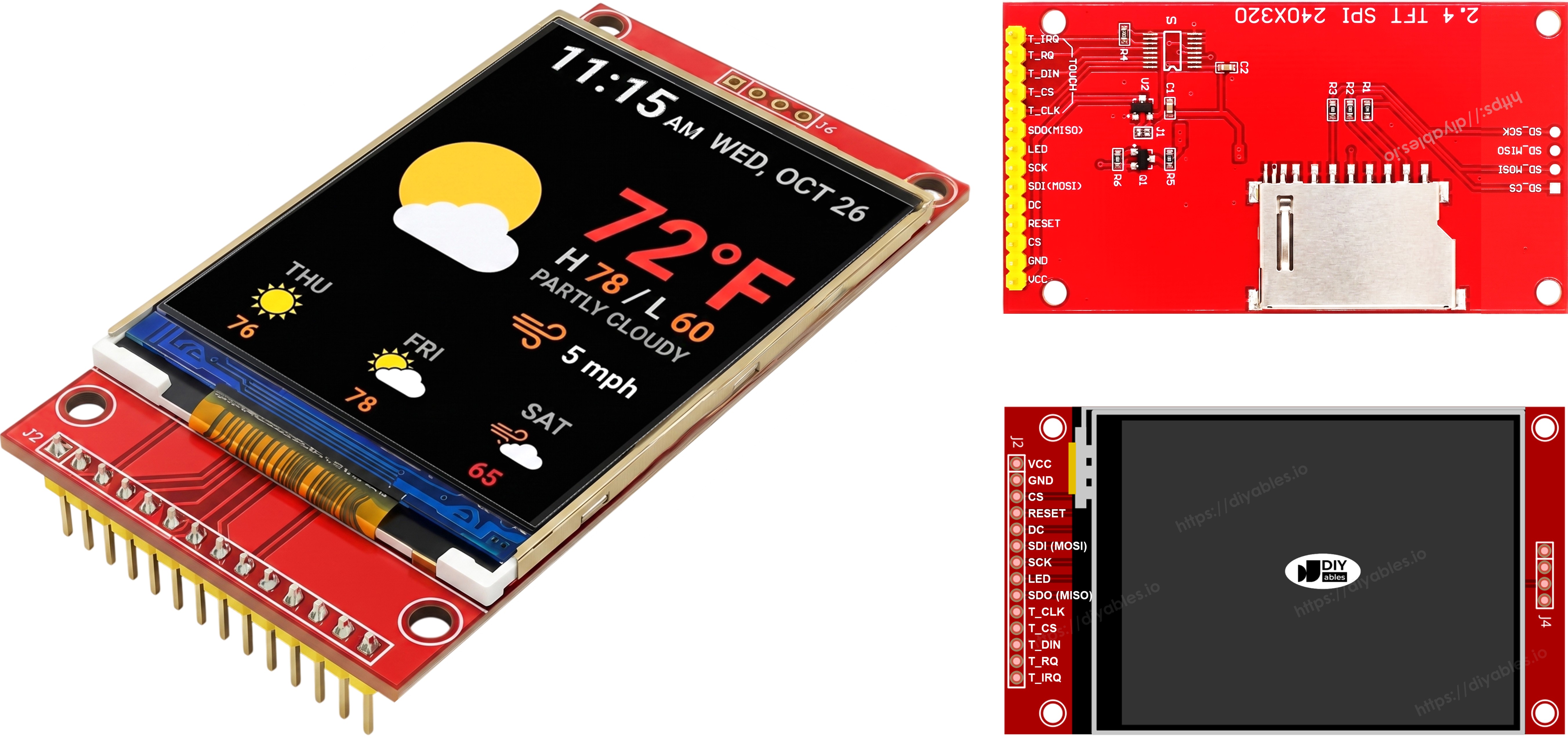
Pinbelegung
Die meisten SPI TFT LCD Displays haben die folgenden Pins:
Display-Pins:
| Pin | Funktion |
|---|---|
| VCC | Stromversorgung |
| GND | Masse |
| CS | Chip Select — wird zum Auswählen des Displays auf dem SPI-Bus auf niedrig gezogen |
| DC / RS | Daten / Befehl Auswahl — hoch für Pixeldaten, niedrig für Befehle |
| RST | Hardware-Reset — optional; an 3,3V anschließen, wenn nicht verwendet |
| MOSI / SDI / SDA | SPI Dateneingabe (MCU → Display) |
| SCK / CLK | SPI Takt |
| MISO / SDO | SPI Datenausgabe (Display → MCU) — optional für nur Display-Betrieb |
| LED / BL / BLK | Hintergrundbeleuchtung Stromversorgung — an 3,3V oder PWM-Pin anschließen für Dimmung |
SD-Kartenstifte (falls Ihre Anwendung Zugriff auf die SD-Karte benötigt):
| Pin | Funktion |
|---|---|
| SD_CS / TF_CS | SD-Karten Chip Select |
| MOSI / SDI | MOSI — Daten vom MCU zur SD-Karte |
| SCK / CLK | SCK — SPI Takt |
| MISO / SDO | MISO — Daten von der SD-Karte zum MCU |
Für TFT Displays, die Touch unterstützen, gibt es zusätzliche Touch-Stifte (falls Ihre Anwendung die Touch-Funktion verwendet und das Display diese unterstützt):
| Pin | Funktion |
|---|---|
| T_CS | Touch-Controller Chip Select |
| T_CLK | SCK — SPI Takt |
| T_DIN | MOSI — Daten vom MCU zum Touch-Controller |
| T_DO | MISO — Daten vom Touch-Controller zum MCU |
| T_IRQ | Touch-Interrupt — optional; signalisiert, wenn der Bildschirm berührt wird |
Hinweis: Einige Nicht-Touch-Display-Module stellen auch T_CS, T_CLK, T_DIN, T_DO und T_IRQ Stifte zur Verfügung. Diese sind auf diesen Platinen nicht funktionsfähig — der Touch-Controller-IC ist nicht bestückt. Sie erscheinen, weil die Platine das gleiche Layout wie die Touch-aktivierte Version wiederverwendet, um Fertigungsvarianten zu reduzieren.
Verdrahtungsdiagramm
Ohne Touch
Verbinden Sie MOSI mit D11, SCK mit D13, MISO mit D12 auf dem Nano ESP32. CS, DC und RST können beliebige verfügbare GPIOs sein — D10, D9, D8 werden in den Beispielen verwendet.
Display:
| TFT-Pin | Arduino Nano ESP32 Pin | Beschreibung |
|---|---|---|
| VCC | 3,3V | Stromversorgung (nur 3,3V) |
| GND | GND | Masse |
| CS | D10 | Chip Select |
| DC / RS | D9 | Daten / Befehl Auswahl |
| RST | D8 | Reset (optional) |
| MOSI / SDI | D11 | Hardware SPI MOSI |
| SCK | D13 | Hardware SPI Takt |
| MISO / SDO | D12 | Hardware SPI MISO (optional) |
| LED / BL | 3,3V | Hintergrundbeleuchtung Stromversorgung |
SD-Karte (falls Ihre Anwendung Zugriff auf die SD-Karte benötigt):
| SD-Pin | Arduino Nano ESP32 Pin | Beschreibung |
|---|---|---|
| SD_CS / TF_CS | beliebiger freier GPIO | SD-Karten Chip Select |
| MOSI / SDI | D11 | Gemeinsam mit Display MOSI (D11) |
| SCK / CLK | D13 | Gemeinsam mit Display SCK (D13) |
| MISO / SDO | D12 | Gemeinsam mit Display MISO (D12) |
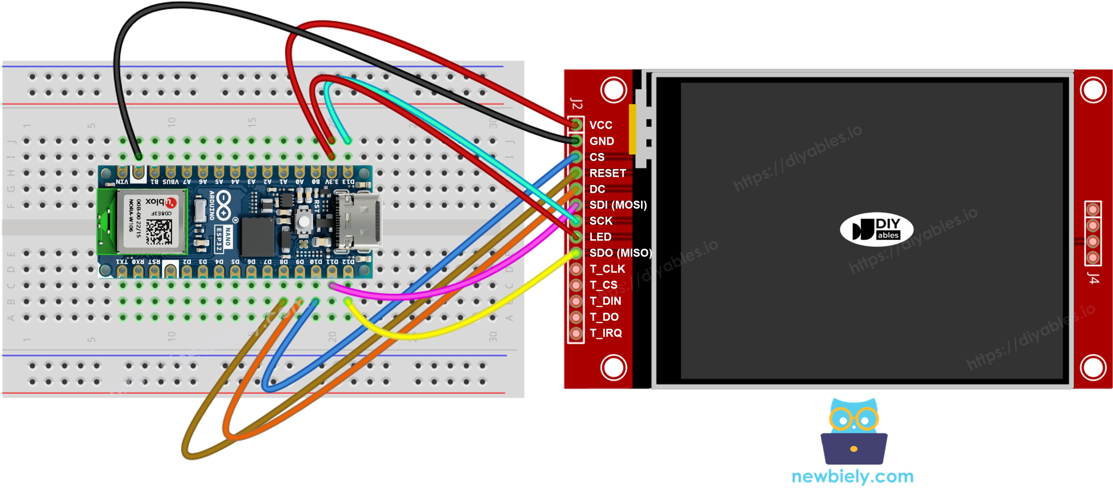
Dieses Bild wurde mit Fritzing erstellt. Klicken Sie, um das Bild zu vergrößern.
Mit Touch
Verbinden Sie den XPT2046 Touch-Controller mit dem Arduino Nano ESP32 SPI-Bus, wobei D11, D13 und D12 mit dem Display geteilt werden.
Display:
| TFT-Pin | Arduino Nano ESP32 Pin | Beschreibung |
|---|---|---|
| VCC | 3,3V | Stromversorgung (nur 3,3V) |
| GND | GND | Masse |
| CS | D10 | Chip Select |
| DC / RS | D9 | Daten / Befehl Auswahl |
| RST | D8 | Reset (optional) |
| MOSI / SDI | D11 | Hardware SPI MOSI |
| SCK | D13 | Hardware SPI Takt |
| MISO / SDO | D12 | Hardware SPI MISO (optional) |
| LED / BL | 3,3V | Hintergrundbeleuchtung Stromversorgung |
Touch-Controller (falls Ihre Anwendung die Touch-Funktion verwendet und das Display diese unterstützt):
| Touch-Pin | Arduino Nano ESP32 Pin | Beschreibung |
|---|---|---|
| T_CS | D7 | Touch Chip Select |
| T_IRQ | D6 | Touch-Interrupt (optional) |
| T_DIN | D11 | Gemeinsam mit Display MOSI (D11) |
| T_CLK | D13 | Gemeinsam mit Display SCK (D13) |
| T_DO | D12 | Gemeinsam mit Display MISO (D12) |
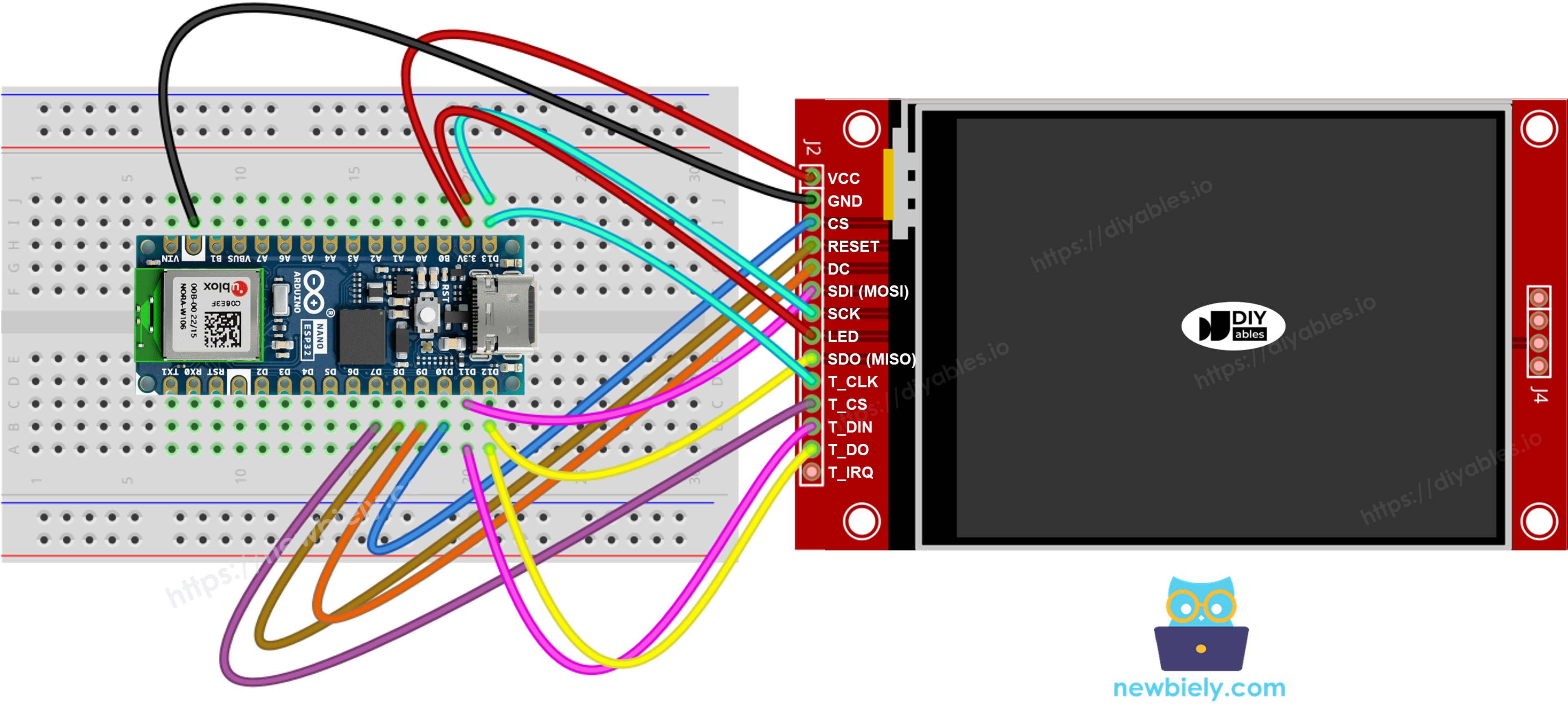
Dieses Bild wurde mit Fritzing erstellt. Klicken Sie, um das Bild zu vergrößern.
Falls Ihr MCU zwei oder mehr Hardware-SPI-Schnittstellen hat, können Sie jedes Peripheriegerät (Display, SD-Karte, Touch-Controller) seinem eigenen dedizierten SPI-Bus zuweisen. Falls Ihr MCU nur eine Hardware-SPI-Schnittstelle hat, teilen sich alle drei Peripheriegeräte die gleichen drei Datenleitungen (MOSI, SCK, MISO) — auf dem Nano ESP32 sind dies D11, D13 und D12. Jedes Peripheriegerät hat seinen eigenen CS-Pin, daher ist nur einer gleichzeitig aktiv. Die DIYables_TFT_SPI Bibliothek verwaltet sowohl das Display als auch den XPT2046 Touch-Controller durch eine einzige API — es ist keine separate SPI-Bibliothek für die Touch-Seite erforderlich.
Bibliotheks-Setup
- Stecken Sie den Arduino Nano ESP32 über seinen USB-C-Anschluss in Ihren Computer ein.
- Öffnen Sie die Arduino IDE. Wählen Sie Arduino Nano ESP32 aus der Platinenliste und wählen Sie den richtigen Port aus.
- Klicken Sie auf das Bibliotheken Symbol in der linken Seitenleiste.
- Geben Sie "DIYables_TFT_SPI" im Suchfeld ein. Suchen Sie nach dem DIYables Eintrag.
- Klicken Sie auf Installieren. Installieren Sie alle Abhängigkeiten, wenn Sie dazu aufgefordert werden.
- Search for DIYables TFT SPI created by DIYables.io and click the Install button.
Starter-Skizze
Der minimale Code, der benötigt wird, um mit der DIYables_TFT_SPI Bibliothek zu beginnen:
Workshop - Formen zeichnen
Das DrawShapes-Beispiel setzt alle Adafruit GFX Zeichenfunktionen ein: Kreise, Rechtecke, Dreiecke und Linien auf dem Bildschirm.
Hands-On
- Verbinden Sie das TFT-Modul mit dem Nano ESP32 unter Verwendung der obigen Tabelle. Verwenden Sie 3,3V für VCC.
- Verbinden Sie den Nano ESP32 über USB-C mit Ihrem Computer.
- Wählen Sie in der Arduino IDE die Platine und den Port, fügen Sie den Code ein und klicken Sie auf Upload.
- Das Display zeigt ein rotierendes Muster aus farbigen Formen.
Methoden-Referenz
| Methode | Aktion | Syntax |
|---|---|---|
| begin() | Initialisiert und setzt das Display zurück. | TFT_display.begin(); |
| setRotation(r) | Stellt die Ausrichtung ein (0=Hochformat, 1=Querformat). | TFT_display.setRotation(1); |
| fillScreen(color) | Löscht den Bildschirm in einer Farbe. | TFT_display.fillScreen(BLACK); |
| colorRGB(r,g,b) | Erstellt eine 16-Bit-Farbe aus R, G, B. | colorRGB(255,128,0) |
| fillCircle(x,y,r,color) | Gefüllter Kreis. | TFT_display.fillCircle(100,100,50,RED); |
| fillRoundRect(x,y,w,h,r,color) | Gefülltes Rechteck mit runden Ecken. | TFT_display.fillRoundRect(10,10,100,50,10,BLUE); |
| drawTriangle(x0,y0,x1,y1,x2,y2,color) | Dreieck-Kontur. | TFT_display.drawTriangle(60,10,10,110,110,110,GREEN); |
Workshop - Text und Zahlen anzeigen
Das ShowTextAndNumber-Beispiel druckt Zeichenketten und Zahlen mit der integrierten GFX-Text-Engine mit einstellbarer Größe und Farbe.
Hands-On
- Verbinden Sie und laden Sie wie oben hochgegeben.
- Das Display druckt mehrere Textzeilen in verschiedenen Farben und Größen.
Methoden-Referenz
| Methode | Aktion | Syntax |
|---|---|---|
| setTextColor(color) | Stellt die Vordergrundfarbe für die Textausgabe ein. | TFT_display.setTextColor(WHITE); |
| setTextSize(size) | Skaliert den Text um einen ganzzahligen Faktor. Größe 1 = 6×8 px. | TFT_display.setTextSize(2); |
| setCursor(x, y) | Bewegt den Text-Cursor zur Pixelposition (x, y). | TFT_display.setCursor(10, 20); |
| print(value) | Druckt eine Zeichenkette oder Zahl an der Cursor-Position. | TFT_display.print("ESP32-S3!"); |
| println(value) | Druckt und bewegt den Cursor zur nächsten Zeile. | TFT_display.println(42); |
Workshop - Bild zeichnen
In dieser Workshop-Station laden Sie ein vollständiges RGB565 Bitmap-Bild auf das Display. Die Pixeldaten werden als PROGMEM-Array in bitmap.h in die Firmware kompiliert. Auf dem ESP32-S3 werden PROGMEM-Daten im Flash gespeichert und in den Adressraum abgebildet, daher wird kein SRAM durch die Bilddaten selbst verbraucht. Fügen Sie bitmap.h dem Sketch-Ordner vor dem Kompilieren hinzu.
Hands-On
- Legen Sie bitmap.h in den gleichen Ordner wie die Skizze.
- Verbinden Sie das TFT-Modul mit dem Nano ESP32. Verwenden Sie 3,3V für VCC.
- Verbinden Sie den Nano ESP32 über USB-C mit Ihrem Computer.
- Wählen Sie in der Arduino IDE die Platine und den Port, fügen Sie den Code ein und klicken Sie auf Upload.
- Das Display zeigt das Bitmap-Bild aus dem Programm-Flash.
Methoden-Referenz
| Methode | Aktion | Syntax |
|---|---|---|
| drawRGBBitmap(x,y,bitmap,w,h) | Zeichnet ein RGB565 PROGMEM Bitmap mit der oberen linken Ecke bei (x, y). | TFT_display.drawRGBBitmap(0, 0, myImage, 240, 320); |
| fillScreen(color) | Löscht den Bildschirm in einer Farbe, bevor das Bitmap gezeichnet wird. | TFT_display.fillScreen(BLACK); |
Workshop - Bild von SD-Karte zeichnen
In dieser Workshop-Station streamen Sie eine rohe RGB565-Bilddatei direkt von einer Micro-SD-Karte zum Display. Der ESP32-S3 verwaltet SD und Display auf dem gleichen SPI-Bus ohne Probleme dank seiner Hardware-SPI-Arbitrierung. Definieren Sie den CS-Pin des SD-Moduls als SD_CS_PIN in der Skizze.
Verbinden Sie das SD-Modul mit den gleichen SPI-Pins wie das Display (D11/D13/D12 auf dem Nano ESP32). Verbinden Sie SD CS mit Ihrem gewählten Pin.
Hands-On
- Verbinden Sie das SD-Modul mit dem Nano ESP32. Teilen Sie MOSI (D11), SCK (D13), MISO (D12) mit dem Display. Verbinden Sie SD CS mit dem als SD_CS_PIN definierten Pin.
- Kopieren Sie ein rohes RGB565 Binärbild auf die Wurzel der SD-Karte. Die Abmessungen müssen der Platine entsprechen.
- Verbinden Sie den Nano ESP32 über USB-C mit Ihrem Computer.
- Wählen Sie in der Arduino IDE die Platine und den Port, fügen Sie den Code ein und klicken Sie auf Upload.
- Das Display rendert das Bild, das von der SD-Karte gestreamt wird.
Methoden-Referenz
| Methode | Aktion | Syntax |
|---|---|---|
| startWrite() | Öffnet eine rohe SPI-Schreib-Sitzung und aktiviert das Display CS. | TFT_display.startWrite(); |
| setAddrWindow(x0,y0,x1,y1) | Stellt die rechteckige Pixel-Region ein, die Daten empfangen soll. | TFT_display.setAddrWindow(0, 0, 239, 319); |
| pushColors(buf, len) | Schreibt einen Puffer von RGB565-Pixelwerten direkt auf die Platine. | TFT_display.pushColors(buf, 512); |
| endWrite() | Schließt die SPI-Sitzung und gibt das Display CS frei. | TFT_display.endWrite(); |
Workshop - Externe Schriftart verwenden
In dieser Workshop-Station ersetzen Sie die Standardraster-Schriftart durch eine schärfere Adafruit GFX-kompatible benutzerdefinierte Schriftart. Der Schriftart-Deskriptor wird als Header-Datei eingefügt. Das Wechseln von Schriftarten zur Laufzeit erfordert nur einen Funktionsaufruf, und Sie können genauso leicht zur integrierten Schriftart zurückwechseln.
Hands-On
- Verbinden Sie das TFT-Modul mit dem Nano ESP32. Verwenden Sie 3,3V für VCC.
- Verbinden Sie den Nano ESP32 über USB-C mit Ihrem Computer.
- Wählen Sie in der Arduino IDE die Platine und den Port, fügen Sie den Code ein und klicken Sie auf Upload.
- Beobachten Sie das Custom-Font-Rendering auf dem Bildschirm. Vergleichen Sie es mit der integrierten Schriftart, um die Verbesserung zu sehen.
Methoden-Referenz
| Methode | Aktion | Syntax |
|---|---|---|
| setFont(&FontName) | Wechselt zu einer benutzerdefinierten GFX-kompatiblen Schriftart. Wenn NULL übergeben wird, wird die integrierte 5×7 Schriftart wiederhergestellt. | TFT_display.setFont(&FreeSans12pt7b); |
| setCursor(x, y) | Positioniert den Text-Cursor an der angegebenen Pixelkoordinate. | TFT_display.setCursor(10, 40); |
| setTextColor(color) | Stellt die Vordergrundfarbe für alle nachfolgenden Textausgaben ein. | TFT_display.setTextColor(WHITE); |
| print(text) | Druckt eine Zeichenkette an der Cursor-Position unter Verwendung der aktiven Schriftart. | TFT_display.print("ESP32 Workshop"); |
Workshop - Touch Punkt lesen
In dieser Workshop-Station lesen Sie rohe ADC-Ausgabe vom XPT2046 Touch-Controller, der mit dem Nano ESP32 verbunden ist. Jeder Touch-Punkt wird auf dem Serial Monitor als rohe X-, Y- und Druck-Z-Werte gedruckt. Diese Zahlen teilen Ihnen den ADC-Bereich mit, den Ihre Platine produziert — essenzielle Information, bevor Sie die Kalibrierung anwenden.
Verdrahtung: Teilen Sie den SPI-Bus (D11/D13/D12) zwischen dem XPT2046 und dem Display. T_CS→D7, T_IRQ→D6. Alle Signale sind bei 3,3V.
Hands-On
- Verbinden Sie den XPT2046 mit dem Nano ESP32, wobei Sie den SPI-Bus mit dem Display teilen. T_CS→D7, T_IRQ→D6.
- Verbinden Sie den Nano ESP32 über USB-C mit Ihrem Computer.
- Wählen Sie in der Arduino IDE die Platine und den Port, fügen Sie den Code ein und klicken Sie auf Upload.
- Öffnen Sie den Serial Monitor bei 9600 Baud. Drücken Sie auf dem Bildschirm, um rohe X-, Y- und Z-Werte zu sehen.
Methoden-Referenz
| Methode | Aktion | Syntax |
|---|---|---|
| initTouchSPI(cs, irq) | Initialisiert den XPT2046 auf dem gemeinsamen SPI-Bus. Übergeben Sie -1 für irq, falls der Interrupt-Pin nicht verbunden ist. | TFT_display.initTouchSPI(7, 6); |
| readTouchRaw(x, y, z) | Liest rohe ADC-Werte vom Controller, wobei die Kalibrierung umgangen wird. Gibt true zurück, wenn gedrückt. | TFT_display.readTouchRaw(x, y, z); |
Workshop - Touch Zeichnen
In dieser Workshop-Station bauen Sie eine Touch-Paint-Anwendung auf dem Nano ESP32. Der XPT2046 liefert kalibrierte Koordinaten, die zu Pixelpositionen übersetzt werden, und an jedem Punkt wird ein kleiner gefüllter Kreis gezeichnet. Ziehen Sie einen Finger, um einen kontinuierlichen bemalten Strich zu erstellen.
Hands-On
- Verbinden Sie den XPT2046 mit dem Nano ESP32, wie in der Workshop-Station Touch Punkt lesen oben beschrieben.
- Verbinden Sie den Nano ESP32 über USB-C mit Ihrem Computer.
- Wählen Sie in der Arduino IDE die Platine und den Port, fügen Sie den Code ein und klicken Sie auf Upload.
- Berühren und ziehen Sie einen Finger über das Display, um auf dem Bildschirm zu zeichnen.
Methoden-Referenz
| Methode | Aktion | Syntax |
|---|---|---|
| initTouchSPI(cs, irq) | Startet den XPT2046 auf dem gemeinsamen SPI-Bus. | TFT_display.initTouchSPI(7, 6); |
| setTouchCalibration(minX,maxX,minY,maxY) | Ordnet rohe ADC-Messwerte den Bildschirm-Pixelkoordinaten zu. Erhalten Sie die vier Werte von der TouchCalibration-Station. | TFT_display.setTouchCalibration(200, 3800, 300, 3700); |
| setTouchInvertX(invert) / setTouchInvertY(invert) | Spiegelt die Touch-Achse, wenn X oder Y auf Ihrem spezifischen Panel oder Batch gespiegelt ist. Rufen Sie VOR setTouchCalibration() auf. | TFT_display.setTouchInvertY(true); |
| getTouch(x, y) | Gibt kalibrierte Touch-Koordinaten in Bildschirm-Pixeln zurück. Gibt true zurück, während der Bildschirm gedrückt wird. | if (TFT_display.getTouch(x, y)) { ... } |
| fillCircle(x, y, r, color) | Zeichnet einen Punkt am Touch-Punkt, um den bemalten Strich aufzubauen. | TFT_display.fillCircle(x, y, 3, RED); |
Workshop - Touch Kalibrierung
In dieser Workshop-Station kalibrieren Sie den XPT2046 Touch-Controller für Ihren spezifischen Panel. Berühren Sie jede Ecke des Bildschirms, wenn Sie dazu aufgefordert werden, und notieren Sie die minimalen und maximalen X- und Y-Werte, die auf dem Serial Monitor gedruckt werden. Diese vier Nummern sind die Kalibrierungskonstanten, die in allen anderen Touch-Stationen verwendet werden sollen.
Hands-On
- Verbinden Sie den XPT2046 mit dem Nano ESP32, wie in der Workshop-Station Touch Punkt lesen oben beschrieben.
- Verbinden Sie den Nano ESP32 über USB-C mit Ihrem Computer.
- Wählen Sie in der Arduino IDE die Platine und den Port, fügen Sie den Code ein und klicken Sie auf Upload.
- Öffnen Sie den Serial Monitor bei 9600 Baud. Berühren Sie jede Ecke, wenn Sie dazu aufgefordert werden.
- Notieren Sie die vier gedruckten Werte und verwenden Sie sie in setTouchCalibration() in allen anderen Touch-Stationen.
Methoden-Referenz
| Methode | Aktion | Syntax |
|---|---|---|
| initTouchSPI(cs, irq) | Initialisiert den XPT2046 Controller. | TFT_display.initTouchSPI(7, 6); |
| readTouchRaw(x, y, z) | Liest rohe ADC-Werte, um den Kalibrierungsbereich zu messen. | TFT_display.readTouchRaw(x, y, z); |
| setTouchCalibration(minX,maxX,minY,maxY) | Speichert Kalibrierungskonstanten, damit getTouch() rohe Werte Pixelkoordinaten zuordnet. | TFT_display.setTouchCalibration(200, 3800, 300, 3700); |
| setTouchInvertX(invert) / setTouchInvertY(invert) | Spiegelt die Touch-Achse, wenn X oder Y auf Ihrem spezifischen Panel oder Batch gespiegelt ist. Rufen Sie auf, BEVOR Sie die Kalibrierung durchführen, damit die gespeicherten Werte zu Ihrem Panel passen. | TFT_display.setTouchInvertY(true); |
Workshop - Benutzerdefinierter SPI
In dieser Workshop-Station leiten Sie das Display zu einem nicht-standardmäßigen SPI-Bus um. Der Nano ESP32 basiert auf dem ESP32-S3, der mehrere Hardware-SPI-Controller unterstützt. Das Übergeben einer benutzerdefinierten SPIClass-Instanz an den Konstruktor ermöglicht es Ihnen, das Display an einen beliebigen verfügbaren SPI-Peripheral zuzuweisen — nützlich, wenn der Standard-Bus mit einem Sensor geteilt wird, der unterschiedliche SPI-Modus-Einstellungen erfordert.
Hands-On
- Kommentieren Sie den SPIClass-Konstruktor in der Skizze aus, die dem SPI-Bus entspricht, den Sie verwenden möchten, und verbinden Sie das Display mit den entsprechenden Pins.
- Verbinden Sie den Nano ESP32 über USB-C mit Ihrem Computer.
- Wählen Sie in der Arduino IDE die Platine und den Port, fügen Sie den Code ein und klicken Sie auf Upload.
- Das Display startet auf dem ausgewählten SPI-Bus und rendert ein Farbstangen-Muster, um den Erfolg zu bestätigen.
Methoden-Referenz
| Methode | Aktion | Syntax |
|---|---|---|
| DIYables_ILI9341_SPI(w,h,cs,dc,rst,spi) | Konstruktor, der einen expliziten SPIClass-Zeiger als letztes Argument akzeptiert. Standardmäßig &SPI, wenn weggelassen. | DIYables_ILI9341_SPI tft(240, 320, 10, 9, 8, &SPI); |
| begin() | Initialisiert das Display auf dem konfigurierten SPI-Bus. | TFT_display.begin(); |
Fehlerbehebung
| Problem | Mögliche Ursache | Lösung |
|---|---|---|
| Schwarzer Bildschirm | VCC bei 5V oder CS/DC nicht verbunden | Verwenden Sie 3,3V für VCC; überprüfen Sie die Verdrahtung von CS und DC |
| Müll auf dem Bildschirm | Falscher Treiber-Konstruktor aktiv | Lassen Sie nur einen Konstruktor auskommentiert |
| Bild verrutscht oder fehlt | Falsche Breite oder Höhe im Konstruktor | Passen Sie die Werte an Ihre Panel-Größe an |
| Touch nicht reaktiv | Fehlende Kalibrierung | Führen Sie das TouchCalibration-Beispiel aus und kopieren Sie die Ausgabewerte |
| Upload fehlgeschlagen | Platine im falschen Modus | Halten Sie BOOT, während Sie RESET drücken, versuchen Sie dann erneut hochzuladen |
Plattform-Unterstützung
Die Bibliothek basiert vollständig auf Arduino Standard APIs und unterstützt alle Arduino-kompatiblen Plattformen (architectures=*).