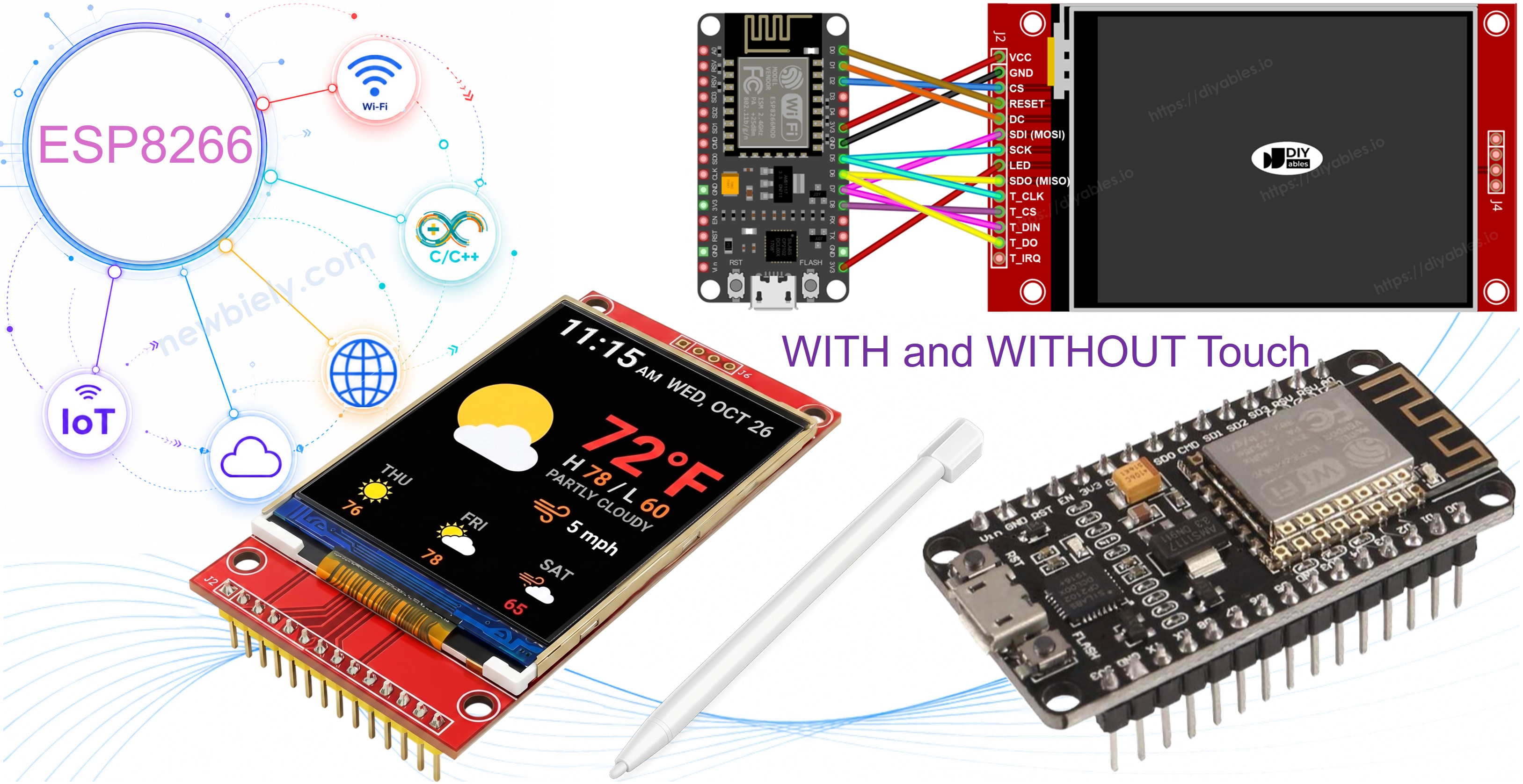
ESP8266 - ILI9341 ILI9488 ST7789 TFT LCD Touch Display SPI Schnittstelle
Dies ist eine praktische, sachliche Anleitung zum Verbinden eines SPI TFT-Displays mit einem ESP8266 NodeMCU Board. Der ESP8266 ist ein kompakter, Wi-Fi-fähiger Mikrocontroller, der mit 80-160 MHz läuft und mit 3,3V arbeitet. Sein Hardware-SPI-Bus befindet sich auf GPIO13 (MOSI), GPIO14 (SCK) und GPIO12 (MISO) - beachten Sie, dass diese NICHT wie bei Arduino Boards als D11/D13/D12 gekennzeichnet sind.
Hier ist, was wir abdecken werden:
- Identifizieren der korrekten SPI-Pins auf dem ESP8266 NodeMCU.
- Verdrahten eines 3,3V SPI TFT-Displays sicher.
- Zeichnen von Formen und Grafiken.
- Anzeigen von Text und Zahlen.
- Zeichnen von Bitmap-Bildern aus dem Programmspeicher (PROGMEM).
- Zeichnen von Bitmap-Bildern, die von einer SD-Karte geladen werden.
- Rendern von Text mit einer benutzerdefinierten externen Schriftart.
- Lesen von Raw-Touch-Koordinaten von einem XPT2046-Controller.
- Zeichnen auf dem Bildschirm durch Touch-Ziehen.
- Erstellen von interaktiven Touch-Buttons.
- Kalibrieren des Touch-Bildschirms.
- Verwenden eines sekundären oder benutzerdefinierten SPI-Bus für das Display.
Dieses Lernprogramm behandelt sowohl Touch- als auch Non-Touch SPI TFT LCD-Displays. Es funktioniert mit 1,3, 1,54, 2,2, 2,4, 2,8, 3,2 und 3,5 Zoll Panels, die von ILI9341, ILI9488 oder ST7789 Controller-Chips gesteuert werden.
Hardware erforderlich
Oder Sie können die folgenden Kits kaufen:
| 1 | × | DIYables Sensor-Kit (18 Sensoren/Displays) |
Das SPI TFT Display
SPI TFT Module verwenden einen dedizierten Driver-IC, um Zeichenbefehle zu empfangen und die LCD-Pixel über einen schnellen SPI-Link zu steuern. Drei Treiber werden unterstützt:
- ILI9341 - 16-Bit RGB565 Farbe, bis zu 40 MHz SPI.
- ILI9488 - 18-Bit RGB666 Farbe über SPI, bis zu 24 MHz.
- ST7789 - 16-Bit RGB565 Farbe, bis zu 40 MHz SPI.
Empfehlung: Wenn Sie noch kein Display gekauft haben, empfehlen wir den ST7789 Treiber. Er ist weit verbreitet, läuft mit voller 40 MHz SPI-Geschwindigkeit und ist die einfachste Wahl für neue Projekte.
Zeichnungsaufrufe erfolgen über die Adafruit GFX API: Formen, Text, Schriftarten und Bitmaps sind alle verfügbar.
Hinweis: Der ESP8266 arbeitet mit 3,3V. Verbinden Sie TFT VCC mit dem 3,3V-Pin. Wenden Sie NICHT 5V an - das beschädigt das Board.
Boot-Pin-Warnung: GPIO0, GPIO2 und GPIO15 beeinflussen den Boot-Modus auf dem ESP8266. Vermeiden Sie deren Verwendung für TFT CS, DC oder RST, um Upload-Fehler zu vermeiden. GPIO4, GPIO5 und GPIO16 sind sichere Optionen.
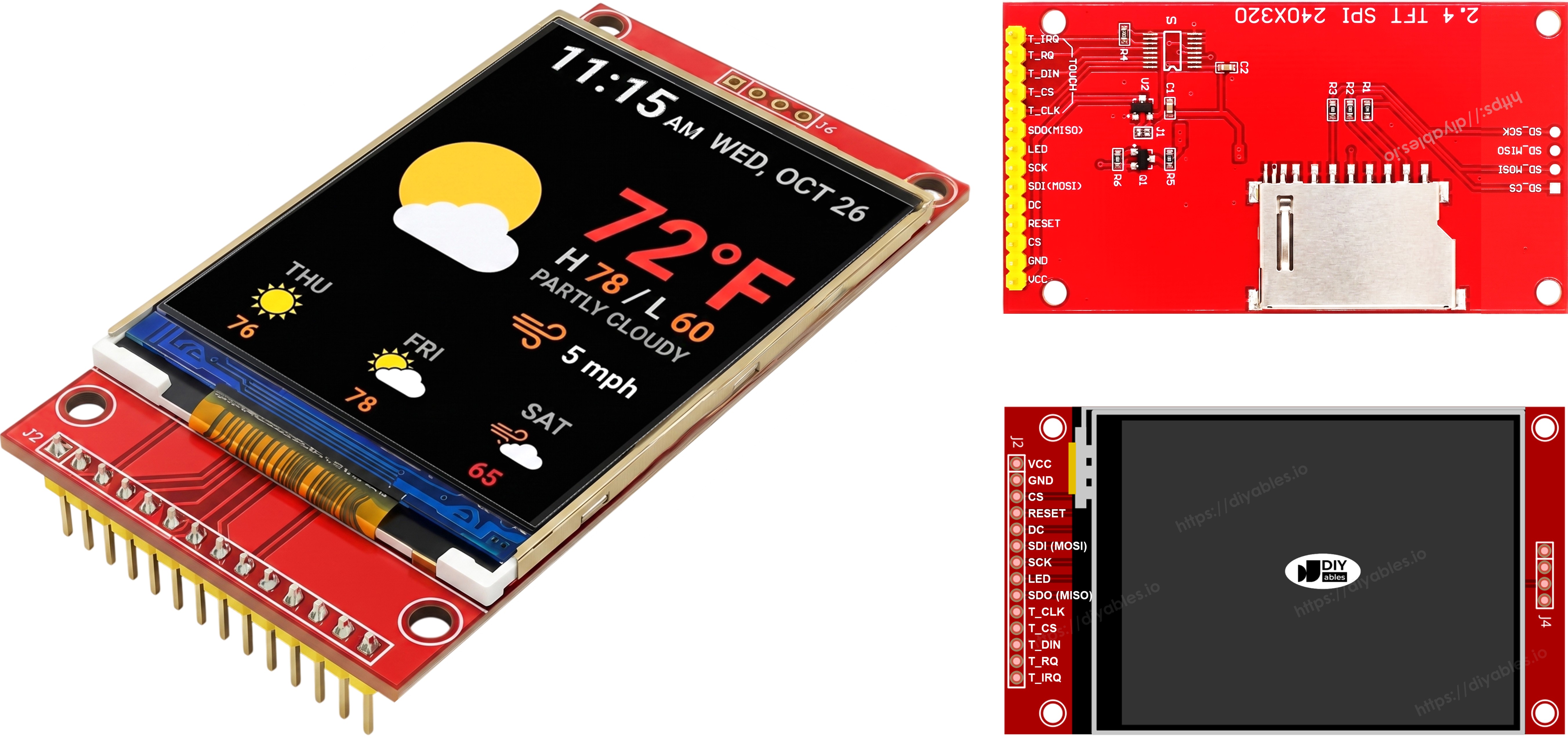
Pinbelegung
Die meisten SPI TFT LCD-Displays haben die folgenden Pins:
Display-Pins:
| Pin | Funktion |
|---|---|
| VCC | Stromversorgung |
| GND | Masse |
| CS | Chip Select — wird niedrig gezogen, um das Display auf dem SPI-Bus auszuwählen |
| DC / RS | Daten- / Befehlsauswahl — hoch für Pixeldaten, niedrig für Befehle |
| RST | Hardware-Reset — optional; auf 3,3V binden, wenn nicht verwendet |
| MOSI / SDI / SDA | SPI-Dateneingang (MCU → Display) |
| SCK / CLK | SPI-Takt |
| MISO / SDO | SPI-Datenausgang (Display → MCU) — optional für reinen Display-Betrieb |
| LED / BL / BLK | Backlight-Stromversorgung — mit 3,3V oder PWM-Pin für Dimmung verbinden |
SD-Karten-Pins (wenn Ihre Anwendung auf die SD-Karte zugreifen muss):
| Pin | Funktion |
|---|---|
| SD_CS / TF_CS | SD-Karten-Chip-Select |
| MOSI / SDI | MOSI — Daten von MCU zu SD-Karte |
| SCK / CLK | SCK — SPI-Takt |
| MISO / SDO | MISO — Daten von SD-Karte zu MCU |
Für TFT-Displays, die Touch unterstützen, gibt es zusätzliche Touch-Pins (wenn Ihre Anwendung die Touch-Funktion nutzt und das Display diese unterstützt):
| Pin | Funktion |
|---|---|
| T_CS | Touch-Controller-Chip-Select |
| T_CLK | SCK — SPI-Takt |
| T_DIN | MOSI — Daten von MCU zu Touch-Controller |
| T_DO | MISO — Daten von Touch-Controller zu MCU |
| T_IRQ | Touch-Interrupt — optional; signalisiert, wenn der Bildschirm berührt wird |
Hinweis: Einige Non-Touch-Display-Module zeigen auch T_CS, T_CLK, T_DIN, T_DO und T_IRQ Pins. Diese funktionieren auf diesen Boards nicht — der Touch-Controller IC ist nicht bestückt. Sie erscheinen, weil die Leiterplatte das gleiche Layout wie die Touch-fähige Version wiederverwendet, um Fertigungsvarianten zu reduzieren.
Schaltschema
Ohne Touch
Verbinden Sie MOSI mit D7 (GPIO13), SCK mit D5 (GPIO14), MISO mit D6 (GPIO12) auf dem ESP8266 NodeMCU. CS, DC und RST können ein beliebiger verfügbarer Boot-sicherer GPIO sein — D2 (GPIO4), D1 (GPIO5), D0 (GPIO16) werden in den Beispielen verwendet.
Display:
| TFT Pin | ESP8266 NodeMCU Pin | GPIO Nummer | Beschreibung |
|---|---|---|---|
| VCC | 3V3 | - | Stromversorgung (nur 3,3V) |
| GND | GND | - | Masse |
| CS | D2 | GPIO4 | Chip Select (Boot-sicher) |
| DC / RS | D1 | GPIO5 | Daten- / Befehlsauswahl (Boot-sicher) |
| RST | D0 | GPIO16 | Reset (Boot-sicher, optional) |
| MOSI / SDI | D7 | GPIO13 | Hardware SPI MOSI |
| SCK | D5 | GPIO14 | Hardware SPI Takt |
| MISO / SDO | D6 | GPIO12 | Hardware SPI MISO (optional) |
| LED / BL | 3V3 | - | Backlight-Stromversorgung |
SD-Karte (wenn Ihre Anwendung auf die SD-Karte zugreifen muss):
| SD Pin | ESP8266 NodeMCU Pin | GPIO Nummer | Beschreibung |
|---|---|---|---|
| SD_CS / TF_CS | D8 | GPIO15 | SD-Karten-Chip-Select (Boot-empfindlich — siehe Hinweis unten) |
| MOSI / SDI | D7 | GPIO13 | Gemeinsam mit Display MOSI (D7/GPIO13) |
| SCK / CLK | D5 | GPIO14 | Gemeinsam mit Display SCK (D5/GPIO14) |
| MISO / SDO | D6 | GPIO12 | Gemeinsam mit Display MISO (D6/GPIO12) |
⚠ Boot-Pin-Hinweis (SD_CS): GPIO15 (D8) muss beim Boot LOW sein. Es wird für SD_CS in diesen Beispielen verwendet. Standard-SD-Module haben einen Pull-Down-Widerstand, der dies automatisch erfüllt. Wenn Uploads nach dem Hinzufügen des SD-Moduls nicht mehr funktionieren, trennen Sie die SD_CS-Leitung und versuchen Sie es erneut.
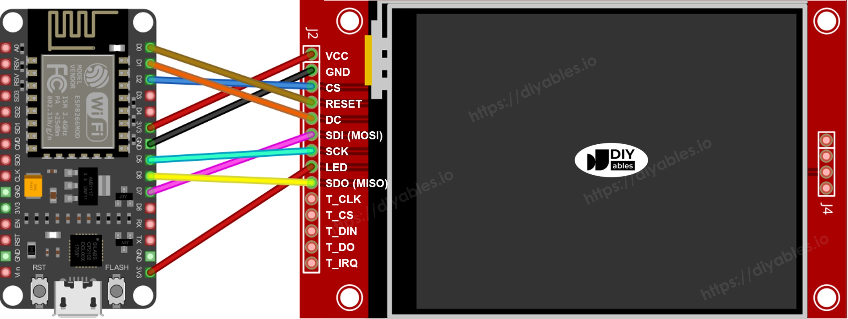
Dieses Bild wurde mit Fritzing erstellt. Klicken Sie, um das Bild zu vergrößern.
Weitere Informationen finden Sie unter ESP8266-Pinbelegung und wie man ESP8266 und andere Komponenten mit Strom versorgt.
Mit Touch
Verbinden Sie den XPT2046 Touch-Controller mit dem ESP8266 NodeMCU SPI-Bus und teilen Sie D7 (GPIO13), D5 (GPIO14) und D6 (GPIO12) mit dem Display.
Display:
| TFT Pin | ESP8266 NodeMCU Pin | GPIO Nummer | Beschreibung |
|---|---|---|---|
| VCC | 3V3 | - | Stromversorgung (nur 3,3V) |
| GND | GND | - | Masse |
| CS | D2 | GPIO4 | Chip Select (Boot-sicher) |
| DC / RS | D1 | GPIO5 | Daten- / Befehlsauswahl (Boot-sicher) |
| RST | D0 | GPIO16 | Reset (Boot-sicher, optional) |
| MOSI / SDI | D7 | GPIO13 | Hardware SPI MOSI |
| SCK | D5 | GPIO14 | Hardware SPI Takt |
| MISO / SDO | D6 | GPIO12 | Hardware SPI MISO (optional) |
| LED / BL | 3V3 | - | Backlight-Stromversorgung |
Touch-Controller (wenn Ihre Anwendung die Touch-Funktion nutzt und das Display diese unterstützt):
| Touch Pin | ESP8266 NodeMCU Pin | GPIO Nummer | Beschreibung |
|---|---|---|---|
| T_CS | D3 | GPIO0 | Touch-Chip-Select (Boot-empfindlich — siehe Hinweis unten) |
| T_IRQ | D4 | GPIO2 | Touch-Interrupt, optional (Boot-empfindlich — siehe Hinweis unten) |
| T_DIN | D7 | GPIO13 | Gemeinsam mit Display MOSI (D7/GPIO13) |
| T_CLK | D5 | GPIO14 | Gemeinsam mit Display SCK (D5/GPIO14) |
| T_DO | D6 | GPIO12 | Gemeinsam mit Display MISO (D6/GPIO12) |
⚠ Boot-Pin-Beschränkungs-Hinweis: Der ESP8266 hat nur drei Boot-sichere GPIOs, die nicht Teil des Hardware-SPI-Bus sind: GPIO4 (D2), GPIO5 (D1) und GPIO16 (D0). Diese sind bereits von TFT CS, DC und RST belegt. Jeder zusätzliche CS-Pin (TOUCH_CS, SD_CS) und das optionale TOUCH_IRQ müssen daher einen der Boot-empfindlichen Pins verwenden:
- GPIO0 / D3 — muss beim Boot HIGH sein. Wird für TOUCH_CS in diesen Beispielen verwendet.
- GPIO2 / D4 — muss beim Boot HIGH sein. Wird für TOUCH_IRQ in diesen Beispielen verwendet.
- GPIO15 / D8 — muss beim Boot LOW sein. Wird für SD_CS in diesen Beispielen verwendet.
Diese Pins sind zur Laufzeit vollständig nutzbar. Die Onboard-Widerstände des NodeMCU Board erfüllen normalerweise die Boot-Anforderungen. Wenn ein Modul jedoch einen dieser Pins während des Einschaltens oder Zurücksetzen aktiv auf die falsche Ebene treibt, startet das Board im Flash-Modus statt Ihren Sketch auszuführen. Wenn Uploads nach dem Hinzufügen eines Touch- oder SD-Moduls nicht mehr funktionieren, trennen Sie die CS-Leitung des Moduls und versuchen Sie den Upload erneut, dann verbinden Sie sie wieder.
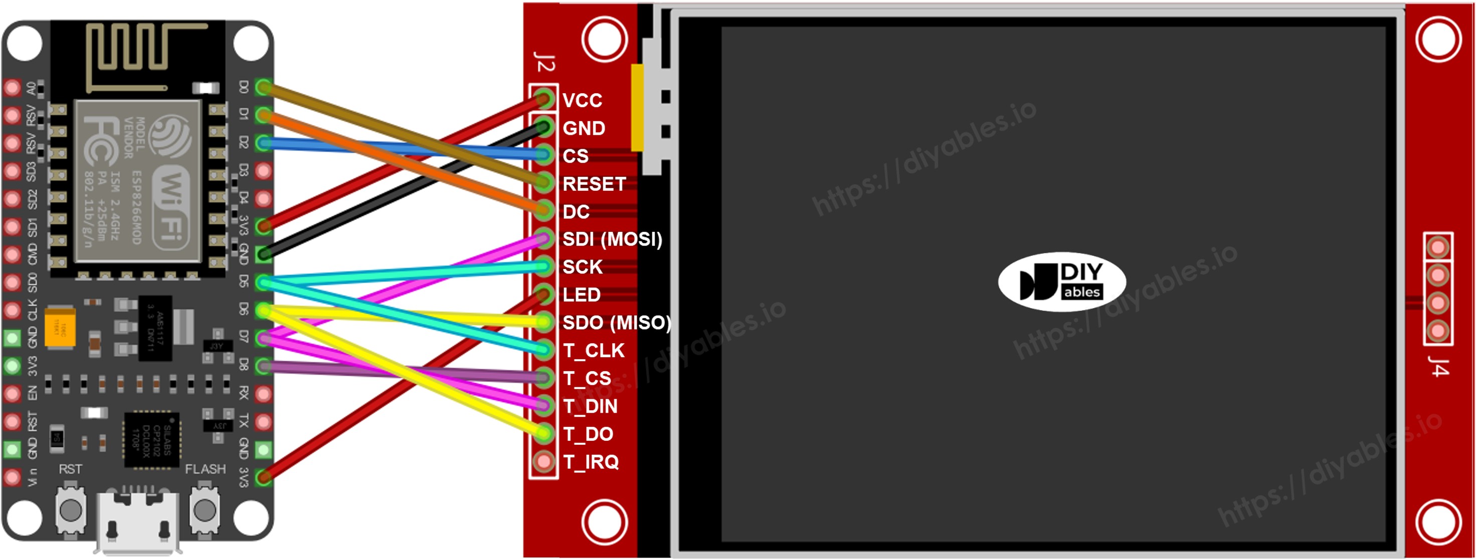
Dieses Bild wurde mit Fritzing erstellt. Klicken Sie, um das Bild zu vergrößern.
Wenn Ihr MCU zwei oder mehr Hardware-SPI-Schnittstellen hat, können Sie jedes Peripheriegerät (Display, SD-Karte, Touch-Controller) seinem eigenen dedizierten SPI-Bus zuweisen. Wenn Ihr MCU nur eine Hardware-SPI-Schnittstelle hat, teilen sich alle drei Peripheriegeräte die gleichen drei Datenleitungen (MOSI, SCK, MISO) — auf dem ESP8266 sind dies D7/GPIO13, D5/GPIO14 und D6/GPIO12. Jedes Peripheriegerät hat seinen eigenen CS-Pin, sodass immer nur einer aktiv ist. Die DIYables_TFT_SPI-Bibliothek verwaltet sowohl das Display als auch den XPT2046 Touch-Controller über eine einzige API — keine separate SPI-Bibliothek ist für die Touch-Seite erforderlich.
Bibliotheksinstallation
- Verbinden Sie den NodeMCU mit Ihrem Computer über ein Micro-B USB-Kabel.
- Öffnen Sie Arduino IDE. Wählen Sie NodeMCU 1.0 (ESP-12E Module) aus der Board-Liste und wählen Sie den richtigen Port.
- Öffnen Sie das Bibliotheken Panel.
- Geben Sie "DIYables_TFT_SPI" in der Suchleiste ein und finden Sie den DIYables Eintrag.
- Klicken Sie auf Installieren. Akzeptieren Sie alle Abhängigkeitsinstallationen.
- Search for DIYables TFT SPI created by DIYables.io and click the Install button.
Startercode
Jeder ESP8266 TFT-Sketch beginnt mit dieser Grundlage:
Probieren Sie es aus - Zeichnen Sie Formen
Das DrawShapes-Beispiel zeichnet Kreise, Dreiecke, Rechtecke, abgerundete Rechtecke und Linien unter Verwendung der Adafruit GFX-Zeichen-API.
Führen Sie den Code aus
- Verdrahten Sie das TFT-Modul mit dem NodeMCU unter Verwendung der obigen Tabelle. Stromversorgung nur von 3,3V.
- Stecken Sie das Micro-B USB-Kabel ein.
- Wählen Sie in Arduino IDE das Board und den Port, fügen Sie den Code ein und drücken Sie Hochladen.
- Das Display zeigt ein sich wiederholendes Muster von farbigen Formen.
Zeichenfunktionen
| Methode | Was es zeichnet | Beispiel |
|---|---|---|
| begin() | Das Display initialisieren. | TFT_display.begin(); |
| setRotation(r) | Orientierung 0-3 einstellen. | TFT_display.setRotation(1); |
| fillScreen(color) | Bildschirm mit einfarbiger Farbe ausfüllen. | TFT_display.fillScreen(BLACK); |
| colorRGB(r,g,b) | 16-Bit-Farbe aus R, G, B erstellen. | colorRGB(255,200,0) |
| fillCircle(x,y,r,color) | Ausgefüllter Kreis. | TFT_display.fillCircle(80,80,40,RED); |
| fillRect(x,y,w,h,color) | Ausgefülltes Rechteck. | TFT_display.fillRect(10,10,80,50,BLUE); |
| drawFastHLine(x,y,w,color) | Horizontale Linie (schnell). | TFT_display.drawFastHLine(0,120,240,WHITE); |
Probieren Sie es aus - Text und Zahl anzeigen
Das ShowTextAndNumber-Beispiel rendert Strings und numerische Werte unter Verwendung der Adafruit GFX-Text-Engine.
Führen Sie den Code aus
- Verdrahten und laden Sie wie oben hochgeladen.
- Das Display druckt Textzeilen in verschiedenen Größen und Farben.
Zeichenfunktionen
| Methode | Was es zeichnet | Beispiel |
|---|---|---|
| setTextColor(color) | Legt die Vordergrundfarbe für Text fest. | TFT_display.setTextColor(WHITE); |
| setTextSize(size) | Skaliert Text. Größe 1 = 6×8 px, Größe 2 = 12×16 px. | TFT_display.setTextSize(2); |
| setCursor(x, y) | Positioniert den Text-Cursor bei Pixel (x, y). | TFT_display.setCursor(10, 20); |
| print(value) | Rendert einen String oder eine Zahl am Cursor. | TFT_display.print("NodeMCU!"); |
| println(value) | Rendert und verschiebt den Cursor in die nächste Zeile. | TFT_display.println(42); |
Probieren Sie es aus - Bild zeichnen
Versuchen Sie, ein Bitmap-Bild auf das Display zu laden. Das DrawImage-Beispiel rendert ein Vollfarb-RGB565-Bild, das im Programm-Flash als PROGMEM const uint16_t Array in bitmap.h gespeichert ist. Auf dem ESP8266 wird PROGMEM-Daten im SPI-Flash-Speicher abgelegt und über einen Read-from-Flash-Befehl statt direkter Zeiger-Dereferenzierung zugegriffen. Die DIYables_TFT_SPI-Bibliothek behandelt dies transparent.
Platzieren Sie bitmap.h im selben Ordner wie der Sketch vor dem Kompilieren.
Führen Sie den Code aus
- Kopieren Sie bitmap.h in denselben Ordner wie den Sketch.
- Verdrahten Sie das TFT-Modul mit dem NodeMCU wie oben gezeigt (GPIO13/14/12 für SPI, GPIO4/5/16 für CS/DC/RST). Verwenden Sie 3,3V für VCC.
- Stecken Sie das Micro-B USB-Kabel ein.
- Wählen Sie in Arduino IDE das Board und den Port, drücken Sie Hochladen.
- Das Display zeigt das aus dem Programm-Flash geladene Bitmap-Bild.
Zeichenfunktionen
| Methode | Was es zeichnet | Beispiel |
|---|---|---|
| drawRGBBitmap(x,y,bitmap,w,h) | Rendert ein RGB565 PROGMEM Bitmap mit seiner oberen linken Ecke bei (x, y). Verwenden Sie das PROGMEM Schlüsselwort auf dem Array. | TFT_display.drawRGBBitmap(0, 0, myImage, 240, 320); |
| fillScreen(color) | Malt den gesamten Bildschirm mit einer einfarbigen Farbe, bevor das Zeichnen erfolgt. | TFT_display.fillScreen(BLACK); |
Probieren Sie es aus - Bild von SD-Karte zeichnen
Versuchen Sie, ein Bild von einer SD-Karte zu lesen. Das DrawImageSDcard-Beispiel streamt eine rohe RGB565 Binärdatei von einer Micro-SD-Karte direkt auf das Display mit einem kleinen Puffer. Dies vermeidet die Speicherung des vollständigen Bildes im 80 KB Heap des ESP8266.
Verdrahten Sie das SD-Modul mit dem gleichen SPI-Bus: GPIO13 (MOSI), GPIO14 (SCK), GPIO12 (MISO). Die drei Boot-sicheren GPIOs (GPIO4, GPIO5, GPIO16) sind bereits für TFT CS, DC und RST verwendet. SD_CS muss daher einen Boot-empfindlichen Pin verwenden. Die Beispiele verwenden GPIO15 (D8), das beim Boot LOW sein muss — Standard-SD-Module haben einen Pull-Down-Widerstand, der dies automatisch erfüllt. Siehe die Boot-Pin-Beschränkungs-Hinweis in der Verdrahtungssektion.
Führen Sie den Code aus
- Verdrahten Sie das SD-Modul mit dem NodeMCU und teilen Sie GPIO13/14/12 mit dem Display. Verbinden Sie SD CS mit D8 (GPIO15) wie im Code definiert. GPIO15 muss beim Boot LOW sein — Standard-SD-Module erfüllen dies mit einem On-Board-Pull-Down.
- Kopieren Sie eine rohe RGB565 Binärbild-Datei auf die SD-Karten-Root. Dimensionen müssen mit dem Panel übereinstimmen.
- Stecken Sie das Micro-B USB-Kabel ein.
- Wählen Sie in Arduino IDE das Board und den Port, drücken Sie Hochladen.
- Das Display rendert das von der SD-Karte gestreamte Bild.
Zeichenfunktionen
| Methode | Was es zeichnet | Beispiel |
|---|---|---|
| startWrite() | Öffnet eine direkte SPI-Schreib-Session und setzt den Display-CS (GPIO4). | TFT_display.startWrite(); |
| setAddrWindow(x0,y0,x1,y1) | Legt die rechteckige Region fest, die Pixeldaten empfängt. | TFT_display.setAddrWindow(0, 0, 239, 319); |
| pushColors(buf, len) | Schreibt einen Puffer von RGB565-Pixelwerten auf das Display. Halten Sie den Puffer klein, um innerhalb von Heap-Limits zu bleiben. | TFT_display.pushColors(buf, 256); |
| endWrite() | Schließt die SPI-Session und gibt den CS frei. | TFT_display.endWrite(); |
Probieren Sie es aus - Verwenden Sie eine externe Schriftart
Versuchen Sie, Text mit einer schärferen Schriftart zu rendern. Das UseExternalFont-Beispiel ersetzt die eingebaute 5×7 Pixel-Schriftart durch eine hochwertige Adafruit GFX-kompatible benutzerdefinierte Schriftart. Der Schriftart-Deskriptor wird als Header-Datei eingebunden und mit einem einzelnen Aufruf zu setFont() aktiviert. Rufen Sie setFont(NULL) auf, um zur eingebauten Schriftart zurückzukehren.
Führen Sie den Code aus
- Verdrahten Sie das TFT-Modul mit dem NodeMCU wie in der Verdrahtungssektion beschrieben. Verwenden Sie 3,3V für VCC.
- Stecken Sie das Micro-B USB-Kabel ein.
- Wählen Sie in Arduino IDE das Board und den Port, drücken Sie Hochladen.
- Das Display rendert Text mit der benutzerdefinierten Schriftart. Die Glyphe-Qualität ist deutlich besser als die eingebaute Schriftart.
Zeichenfunktionen
| Methode | Was es zeichnet | Beispiel |
|---|---|---|
| setFont(&FontName) | Wechselt zu einer benutzerdefinierten GFX-Schriftart. Übergeben Sie NULL, um die eingebaute 5×7 Pixel-Schriftart wiederherzustellen. | TFT_display.setFont(&FreeSans12pt7b); |
| setCursor(x, y) | Verschiebt den Text-Cursor zur gegebenen Pixelposition. | TFT_display.setCursor(10, 40); |
| setTextColor(color) | Legt die Text-Vordergrundfarbe fest. | TFT_display.setTextColor(WHITE); |
| print(text) | Druckt einen String am Cursor unter Verwendung der aktiven Schriftart. | TFT_display.print("NodeMCU!"); |