ESP32 Bluetooth Digital Pins Beispiel - Pin-Steuerung und Monitor-Interface Tutorial
Überblick
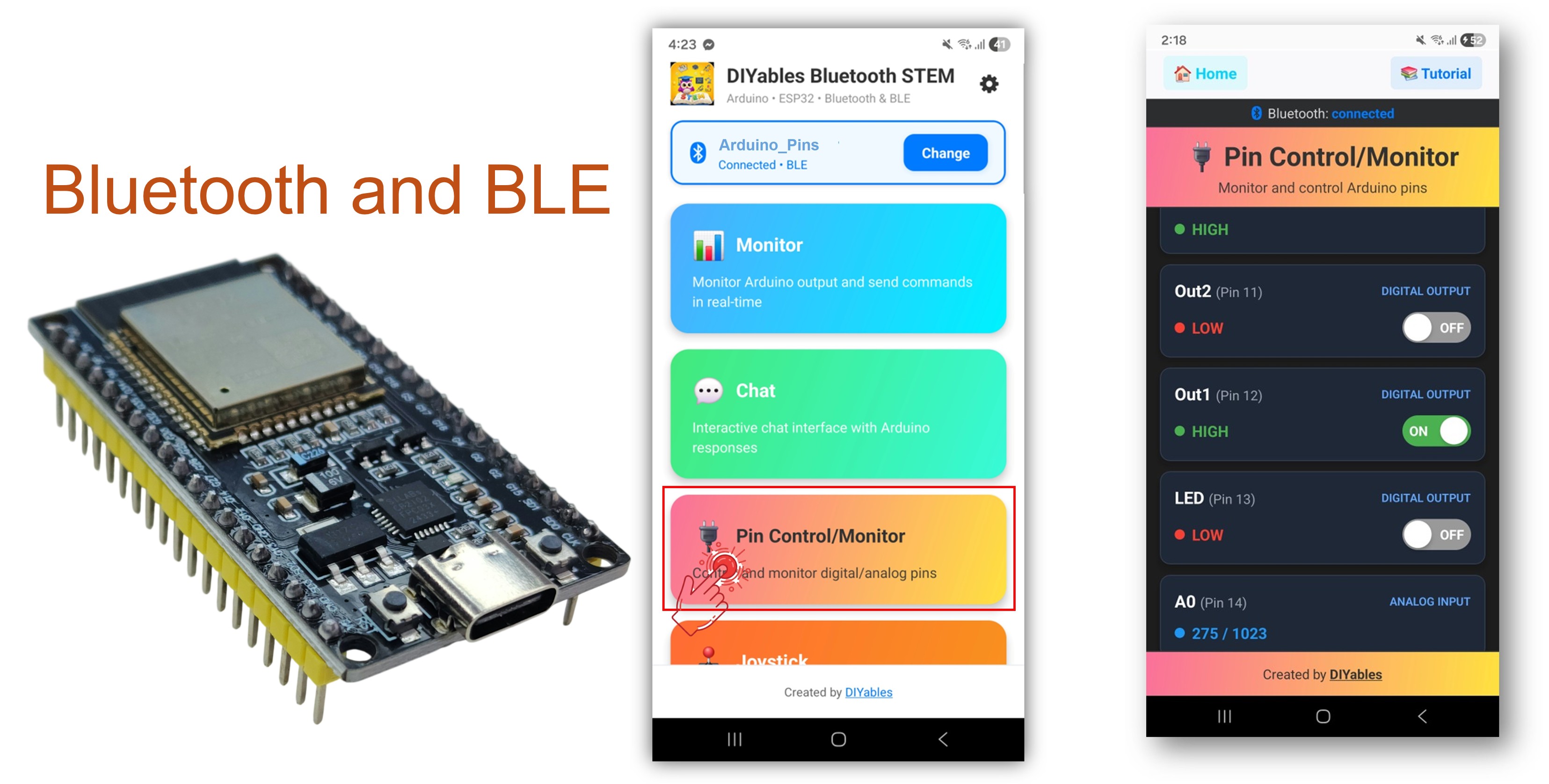
Das Bluetooth Digital Pins Beispiel bietet ferngesteuerte Steuerung und Überwachung von ESP32 GPIO-Pins über die DIYables Bluetooth STEM App. Entwickelt für ESP32-Boards mit Unterstützung für sowohl BLE (Bluetooth Low Energy) als auch Classic Bluetooth Verbindungen. Konfigurieren Sie Pins als Eingänge oder Ausgänge, schalten Sie Ausgangs-Pins um, lesen Sie digitale und analoge Eingangs-Zustände und erhalten Sie Echtzeit-Pin-Änderungs-Benachrichtigungen — perfekt für Hausautomation, Relais-Steuerung, Button-Monitoring und Sensor-Auslesung.
Dieses Beispiel unterstützt zwei Bluetooth-Modi:
ESP32 BLE (Bluetooth Low Energy): Funktioniert sowohl auf Android als auch iOS
ESP32 Classic Bluetooth: Funktioniert nur auf Android. iOS unterstützt Classic Bluetooth nicht. Verwenden Sie BLE, wenn Sie iOS-Unterstützung benötigen.
Features
Ausgangs-Pin-Steuerung: Schalten Sie digitale Ausgangs-Pins HIGH/LOW über die App
Eingangs-Pin-Überwachung: Lesen Sie digitale und analoge Eingangs-Pin-Zustände
Benutzerdefinierte Pin-Namen: Vergeben Sie benutzerfreundliche Namen für jeden Pin (z.B. "LED", "Btn1", "A34")
Echtzeit-Updates: Automatische Benachrichtigungen bei Änderungen der Eingangs-Pin-Zustände
Bis zu 16 Pins: Unterstützung für bis zu 16 konfigurierbare Pins gleichzeitig
Gemischte Modi: Kombinieren Sie Eingangs- und Ausgangs-Pins im gleichen Setup
BLE & Classic Bluetooth: Wählen Sie den Bluetooth-Modus, der zu Ihrem Projekt passt
Plattformübergreifend: BLE-Modus funktioniert sowohl auf Android als auch iOS; Classic Bluetooth funktioniert auf Android
Offenlegung: Einige der in diesem Abschnitt bereitgestellten Links sind Amazon-Affiliate-Links. Wir können eine Provision für Käufe erhalten, die über diese Links getätigt werden, ohne zusätzliche Kosten für Sie. Wir schätzen Ihre Unterstützung.
ESP32 Code
Schnelle Schritte
Befolgen Sie diese Anweisungen Schritt für Schritt:
Verbinden Sie das ESP32-Board mit Ihrem Computer über ein USB-Kabel.
Starten Sie die Arduino IDE auf Ihrem Computer.
Wählen Sie das entsprechende ESP32-Board und den COM-Port aus.
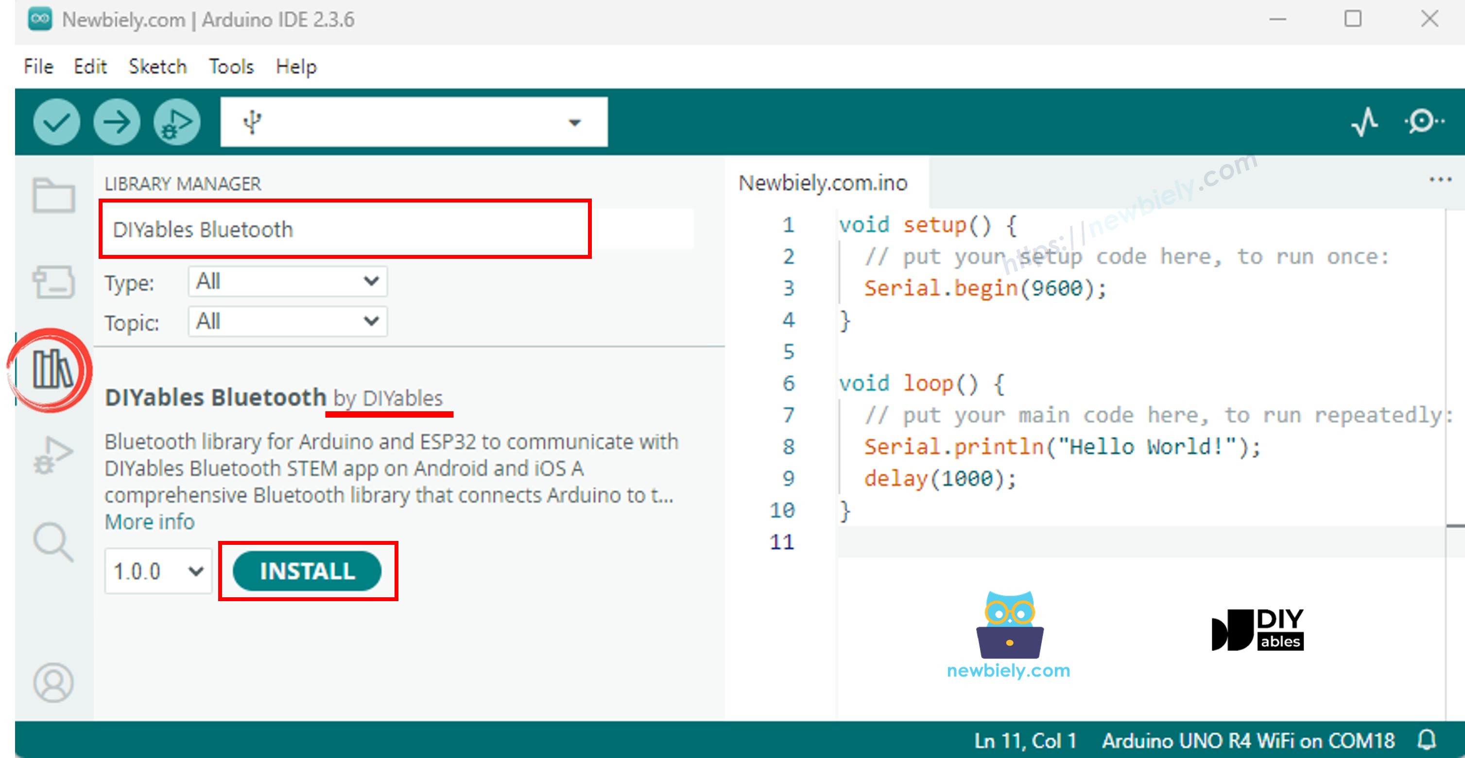
Navigieren Sie zum Libraries-Symbol in der linken Leiste der Arduino IDE.
Suchen Sie nach "DIYables Bluetooth", dann finden Sie die DIYables Bluetooth-Bibliothek von DIYables
Klicken Sie auf Install, um die Bibliothek zu installieren.
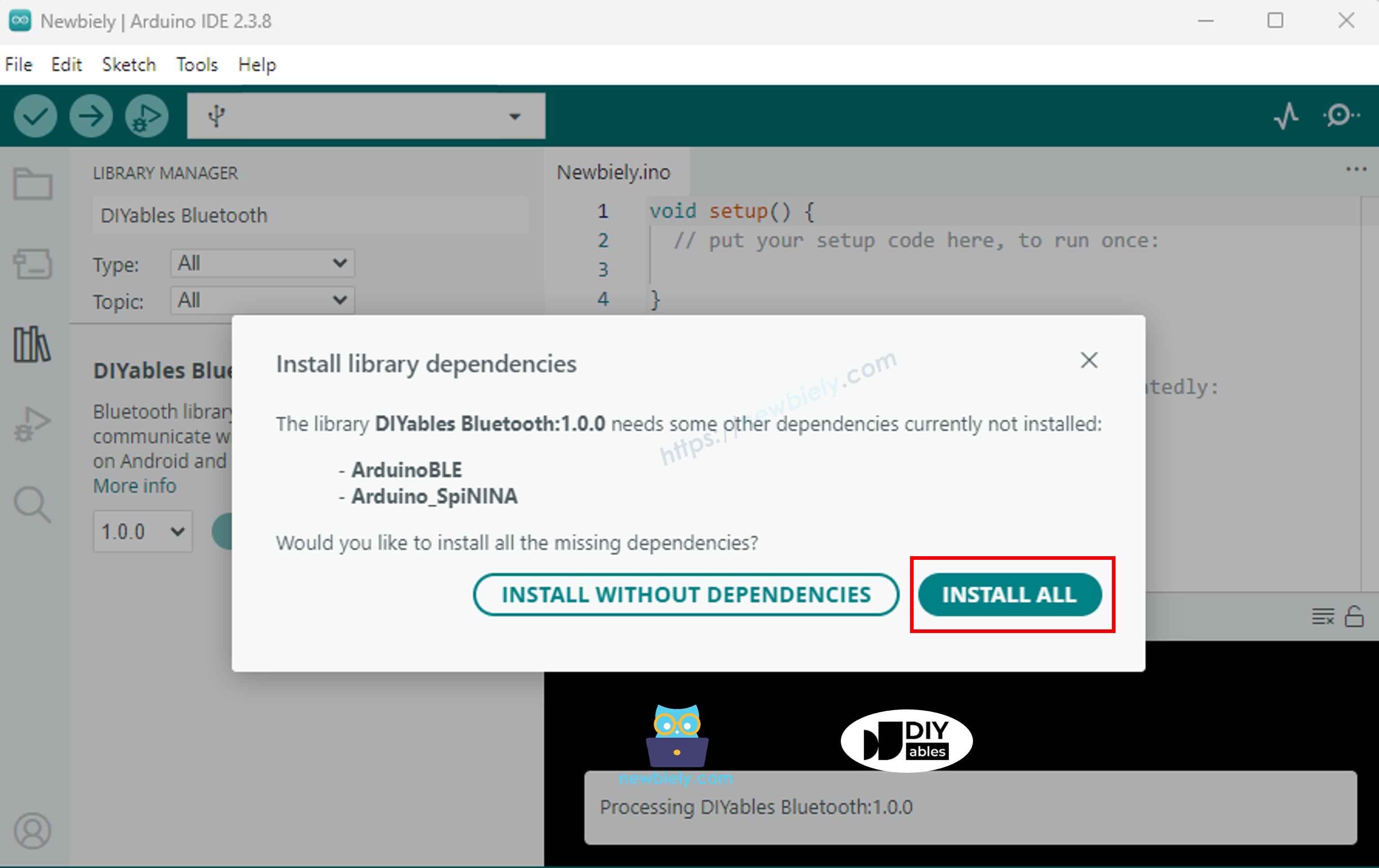
Sie werden nach der Installation einiger anderer Bibliotheks-Abhängigkeiten gefragt
Klicken Sie auf Install All, um alle Bibliotheks-Abhängigkeiten zu installieren.
Wählen Sie einen der beiden Bluetooth-Modi unten, je nach Ihren Anforderungen:
ESP32 Classic Bluetooth Code (funktioniert nur mit der App auf Android)
Hinweis: Classic Bluetooth wird NICHT auf iOS unterstützt. Wenn Sie iOS-Unterstützung benötigen, verwenden Sie den BLE-Code unten.
Gehen Sie in der Arduino IDE zu File Examples DIYables Bluetooth Esp32Bluetooth_PinControl Beispiel, oder kopieren Sie den obigen Code und fügen Sie ihn in den Editor der Arduino IDE ein
/* * DIYables Bluetooth Library - ESP32 Classic Bluetooth Pin Control Example * Works with DIYables Bluetooth STEM app on Android * Note: Classic Bluetooth is NOT supported on iOS. Use BLE examples for iOS support. * * This example demonstrates the Bluetooth Pin Control/Monitor feature: * - Control digital output pins via Bluetooth * - Monitor digital input pins * - Monitor analog input pins * - Configure pin modes (INPUT/OUTPUT) * * Compatible Boards: * - ESP32 (all variants with Classic Bluetooth) * - ESP32-WROOM-32 * - ESP32-DevKitC * - ESP32-WROVER * * Note: Select "Huge APP (3MB No OTA/1MB SPIFFS)" partition scheme * in Arduino IDE: Tools > Partition Scheme * * Setup: * 1. Upload the sketch to your ESP32 * 2. Open Serial Monitor (115200 baud) to see connection status * 3. Use DIYables Bluetooth App to connect and control pins * * Tutorial: https://diyables.io/bluetooth-app * Author: DIYables */#include <DIYables_BluetoothServer.h>#include <DIYables_BluetoothPinControl.h>#include <platforms/DIYables_Esp32Bluetooth.h>// Create Bluetooth instancesDIYables_Esp32Bluetooth bluetooth("ESP32_Pins");DIYables_BluetoothServer bluetoothServer(bluetooth);// Create Pin Control/Monitor app instanceDIYables_BluetoothPinControl bluetoothPins;// Pin configuration (adjust for your ESP32 board)constint LED_PIN = 2; // Built-in LED on most ESP32 boardsconstint OUTPUT_PIN_1 = 16;constint OUTPUT_PIN_2 = 17;constint INPUT_PIN_1 = 18;constint INPUT_PIN_2 = 19;constint ANALOG_PIN_1 = 34; // ESP32 ADC1 pins (input only)constint ANALOG_PIN_2 = 35;voidsetup() {Serial.begin(115200);delay(1000);Serial.println("DIYables Bluetooth - ESP32 Pin Control/Monitor Example");// Initialize pinspinMode(LED_PIN, OUTPUT);pinMode(OUTPUT_PIN_1, OUTPUT);pinMode(OUTPUT_PIN_2, OUTPUT);pinMode(INPUT_PIN_1, INPUT_PULLUP);pinMode(INPUT_PIN_2, INPUT_PULLUP);// Initialize Bluetooth server with platform-specific implementation bluetoothServer.begin();// Add digital pins app to server bluetoothServer.addApp(&bluetoothPins);// Configure which pins are accessible via Bluetooth with custom names bluetoothPins.enablePin(LED_PIN, BT_PIN_OUTPUT, "LED"); bluetoothPins.enablePin(OUTPUT_PIN_1, BT_PIN_OUTPUT, "Out1"); bluetoothPins.enablePin(OUTPUT_PIN_2, BT_PIN_OUTPUT, "Out2"); bluetoothPins.enablePin(INPUT_PIN_1, BT_PIN_INPUT, "Btn1"); bluetoothPins.enablePin(INPUT_PIN_2, BT_PIN_INPUT, "Btn2"); bluetoothPins.enablePin(ANALOG_PIN_1, BT_PIN_INPUT, "A34"); bluetoothPins.enablePin(ANALOG_PIN_2, BT_PIN_INPUT, "A35");// Set up connection event callbacks bluetoothServer.setOnConnected([]() {Serial.println("Bluetooth connected!"); }); bluetoothServer.setOnDisconnected([]() {Serial.println("Bluetooth disconnected!"); });// Set up callback for pin write commands bluetoothPins.onPinWrite([](int pin, int state) {digitalWrite(pin, state);Serial.print("Pin ");Serial.print(pin);Serial.print(" set to ");Serial.println(state ? "HIGH" : "LOW"); });// Set up callback for pin read commands bluetoothPins.onPinRead([](int pin) -> int {// Read analog pins with analogRead, digital pins with digitalReadint state;if (pin == ANALOG_PIN_1 || pin == ANALOG_PIN_2) { state = analogRead(pin);Serial.print("Analog pin ");Serial.print(pin);Serial.print(" read: ");Serial.println(state); } else { state = digitalRead(pin);Serial.print("Digital pin ");Serial.print(pin);Serial.print(" read: ");Serial.println(state ? "HIGH" : "LOW"); }return state; });// Set up callback for pin mode changes bluetoothPins.onPinModeChange([](int pin, int mode) {pinMode(pin, mode == BT_PIN_OUTPUT ? OUTPUT : INPUT_PULLUP);Serial.print("Pin ");Serial.print(pin);Serial.print(" mode changed to ");Serial.println(mode == BT_PIN_OUTPUT ? "OUTPUT" : "INPUT"); });Serial.println("Waiting for Bluetooth connection...");Serial.print("Enabled pins: ");Serial.println(bluetoothPins.getEnabledPinCount());}voidloop() {// Handle Bluetooth server communications bluetoothServer.loop();// Optional: Monitor input pins and send updatesstaticunsignedlong lastInputCheck = 0;staticint lastInputState1 = HIGH;staticint lastInputState2 = HIGH;staticint lastAnalogState1 = 0;staticint lastAnalogState2 = 0;if (millis() - lastInputCheck >= 100) { lastInputCheck = millis();// Check digital input pin 1int currentState1 = digitalRead(INPUT_PIN_1);if (currentState1 != lastInputState1) { lastInputState1 = currentState1; bluetoothPins.updatePinState(INPUT_PIN_1, currentState1);Serial.print("Input pin ");Serial.print(INPUT_PIN_1);Serial.print(" changed to ");Serial.println(currentState1 ? "HIGH" : "LOW"); }// Check digital input pin 2int currentState2 = digitalRead(INPUT_PIN_2);if (currentState2 != lastInputState2) { lastInputState2 = currentState2; bluetoothPins.updatePinState(INPUT_PIN_2, currentState2);Serial.print("Input pin ");Serial.print(INPUT_PIN_2);Serial.print(" changed to ");Serial.println(currentState2 ? "HIGH" : "LOW"); }// Check analog input 1 (send update if changed by more than 50 - ESP32 has 12-bit ADC)int currentAnalog1 = analogRead(ANALOG_PIN_1);if (abs(currentAnalog1 - lastAnalogState1) > 50) { lastAnalogState1 = currentAnalog1; bluetoothPins.updatePinState(ANALOG_PIN_1, currentAnalog1);Serial.print("Analog pin ");Serial.print(ANALOG_PIN_1);Serial.print(" changed to ");Serial.println(currentAnalog1); }// Check analog input 2 (send update if changed by more than 50)int currentAnalog2 = analogRead(ANALOG_PIN_2);if (abs(currentAnalog2 - lastAnalogState2) > 50) { lastAnalogState2 = currentAnalog2; bluetoothPins.updatePinState(ANALOG_PIN_2, currentAnalog2);Serial.print("Analog pin ");Serial.print(ANALOG_PIN_2);Serial.print(" changed to ");Serial.println(currentAnalog2); } }delay(10);}
Klicken Sie auf Upload in der Arduino IDE, um den Code auf den ESP32 hochzuladen
Öffnen Sie den Serial Monitor
Schauen Sie sich das Ergebnis im Serial Monitor an. Es sieht folgendermaßen aus:
Newbiely | Arduino IDE 2.3.8
──
☐
✕
File
Edit
Sketch
Tools
Help
ESP32 Dev Module
Newbiely.ino
···
8Serial.println("Hello World!");
Output
Serial Monitor
Message (Enter to send message to 'ESP32 Dev Module' on 'COM15')
New Line
9600 baud
DIYables Bluetooth - ESP32 Pin Control/Monitor Example
Waiting for Bluetooth connection...
Enabled pins: 7
Ln 11, Col 1
ESP32 Dev Module on COM15
2
ESP32 BLE Code (funktioniert mit der App sowohl auf Android als auch iOS)
Gehen Sie in der Arduino IDE zu File Examples DIYables Bluetooth Esp32BLE_PinControl Beispiel, oder kopieren Sie den obigen Code und fügen Sie ihn in den Editor der Arduino IDE ein
/* * DIYables Bluetooth Library - ESP32 BLE Pin Control/Monitor Example * Works with DIYables Bluetooth STEM app on Android and iOS * * This example demonstrates the Bluetooth Pin Control/Monitor feature: * - Control digital output pins via Bluetooth * - Monitor digital input pins * - Monitor analog input pins * - Configure pin modes (INPUT/OUTPUT) * * Compatible Boards: * - ESP32-WROOM-32 * - ESP32-DevKitC * - ESP32-WROVER * - ESP32-S3 * - ESP32-C3 * - Any ESP32 board supporting BLE * * Note: Select "Huge APP (3MB No OTA/1MB SPIFFS)" partition scheme * in Arduino IDE: Tools > Partition Scheme * * Setup: * 1. Upload the sketch to your ESP32 * 2. Open Serial Monitor (115200 baud) to see connection status * 3. Use DIYables Bluetooth App to connect and control pins * * Tutorial: https://diyables.io/bluetooth-app * Author: DIYables */#include <DIYables_BluetoothServer.h>#include <DIYables_BluetoothPinControl.h>#include <platforms/DIYables_Esp32BLE.h>// BLE Configurationconst char* DEVICE_NAME = "ESP32BLE_Pins";const char* SERVICE_UUID = "19B10000-E8F2-537E-4F6C-D104768A1214";const char* TX_UUID = "19B10001-E8F2-537E-4F6C-D104768A1214";const char* RX_UUID = "19B10002-E8F2-537E-4F6C-D104768A1214";// Create Bluetooth instancesDIYables_Esp32BLE bluetooth(DEVICE_NAME, SERVICE_UUID, TX_UUID, RX_UUID);DIYables_BluetoothServer bluetoothServer(bluetooth);// Create Pin Control/Monitor app instanceDIYables_BluetoothPinControl bluetoothPins;// Pin configuration (ESP32 GPIOs)constint LED_PIN = 2; // Built-in LEDconstint OUTPUT_PIN_1 = 16;constint OUTPUT_PIN_2 = 17;constint INPUT_PIN_1 = 25;constint INPUT_PIN_2 = 26;constint ANALOG_PIN_1 = 34; // Input-only ADC pinconstint ANALOG_PIN_2 = 35; // Input-only ADC pinvoidsetup() {Serial.begin(115200);delay(1000);Serial.println("DIYables Bluetooth - ESP32 BLE Pin Control/Monitor Example");// Initialize pinspinMode(LED_PIN, OUTPUT);pinMode(OUTPUT_PIN_1, OUTPUT);pinMode(OUTPUT_PIN_2, OUTPUT);pinMode(INPUT_PIN_1, INPUT_PULLUP);pinMode(INPUT_PIN_2, INPUT_PULLUP);// Initialize Bluetooth server with platform-specific implementation bluetoothServer.begin();// Add digital pins app to server bluetoothServer.addApp(&bluetoothPins);// Configure which pins are accessible via Bluetooth with custom names bluetoothPins.enablePin(LED_PIN, BT_PIN_OUTPUT, "LED"); bluetoothPins.enablePin(OUTPUT_PIN_1, BT_PIN_OUTPUT, "Out1"); bluetoothPins.enablePin(OUTPUT_PIN_2, BT_PIN_OUTPUT, "Out2"); bluetoothPins.enablePin(INPUT_PIN_1, BT_PIN_INPUT, "Btn1"); bluetoothPins.enablePin(INPUT_PIN_2, BT_PIN_INPUT, "Btn2"); bluetoothPins.enablePin(ANALOG_PIN_1, BT_PIN_INPUT, "A34"); bluetoothPins.enablePin(ANALOG_PIN_2, BT_PIN_INPUT, "A35");// Set up connection event callbacks bluetoothServer.setOnConnected([]() {Serial.println("Bluetooth connected!"); }); bluetoothServer.setOnDisconnected([]() {Serial.println("Bluetooth disconnected!"); });// Set up callback for pin write commands bluetoothPins.onPinWrite([](int pin, int state) {digitalWrite(pin, state);Serial.print("Pin ");Serial.print(pin);Serial.print(" set to ");Serial.println(state ? "HIGH" : "LOW"); });// Set up callback for pin read commands bluetoothPins.onPinRead([](int pin) -> int {int state;if (pin == ANALOG_PIN_1 || pin == ANALOG_PIN_2) { state = analogRead(pin);Serial.print("Analog pin ");Serial.print(pin);Serial.print(" read: ");Serial.println(state); } else { state = digitalRead(pin);Serial.print("Digital pin ");Serial.print(pin);Serial.print(" read: ");Serial.println(state ? "HIGH" : "LOW"); }return state; });// Set up callback for pin mode changes bluetoothPins.onPinModeChange([](int pin, int mode) {pinMode(pin, mode == BT_PIN_OUTPUT ? OUTPUT : INPUT_PULLUP);Serial.print("Pin ");Serial.print(pin);Serial.print(" mode changed to ");Serial.println(mode == BT_PIN_OUTPUT ? "OUTPUT" : "INPUT"); });Serial.println("Waiting for Bluetooth connection...");Serial.print("Enabled pins: ");Serial.println(bluetoothPins.getEnabledPinCount());}voidloop() { bluetoothServer.loop();staticunsignedlong lastInputCheck = 0;staticint lastInputState1 = HIGH;staticint lastInputState2 = HIGH;staticint lastAnalogState1 = 0;staticint lastAnalogState2 = 0;if (millis() - lastInputCheck >= 100) { lastInputCheck = millis();int currentState1 = digitalRead(INPUT_PIN_1);if (currentState1 != lastInputState1) { lastInputState1 = currentState1; bluetoothPins.updatePinState(INPUT_PIN_1, currentState1);Serial.print("Input pin ");Serial.print(INPUT_PIN_1);Serial.print(" changed to ");Serial.println(currentState1 ? "HIGH" : "LOW"); }int currentState2 = digitalRead(INPUT_PIN_2);if (currentState2 != lastInputState2) { lastInputState2 = currentState2; bluetoothPins.updatePinState(INPUT_PIN_2, currentState2);Serial.print("Input pin ");Serial.print(INPUT_PIN_2);Serial.print(" changed to ");Serial.println(currentState2 ? "HIGH" : "LOW"); }// ESP32 has 12-bit ADC (0-4095)int currentAnalog1 = analogRead(ANALOG_PIN_1);if (abs(currentAnalog1 - lastAnalogState1) > 40) { // ~1% of 4095 lastAnalogState1 = currentAnalog1; bluetoothPins.updatePinState(ANALOG_PIN_1, currentAnalog1);Serial.print("Analog pin ");Serial.print(ANALOG_PIN_1);Serial.print(" changed to ");Serial.println(currentAnalog1); }int currentAnalog2 = analogRead(ANALOG_PIN_2);if (abs(currentAnalog2 - lastAnalogState2) > 40) { lastAnalogState2 = currentAnalog2; bluetoothPins.updatePinState(ANALOG_PIN_2, currentAnalog2);Serial.print("Analog pin ");Serial.print(ANALOG_PIN_2);Serial.print(" changed to ");Serial.println(currentAnalog2); } }delay(10);}
Klicken Sie auf Upload in der Arduino IDE, um den Code auf den ESP32 hochzuladen
Öffnen Sie den Serial Monitor
Schauen Sie sich das Ergebnis im Serial Monitor an. Es sieht folgendermaßen aus:
Newbiely | Arduino IDE 2.3.8
──
☐
✕
File
Edit
Sketch
Tools
Help
ESP32 Dev Module
Newbiely.ino
···
8Serial.println("Hello World!");
Output
Serial Monitor
Message (Enter to send message to 'ESP32 Dev Module' on 'COM15')
New Line
9600 baud
DIYables Bluetooth - ESP32 BLE Pin Control/Monitor Example
Waiting for Bluetooth connection...
Enabled pins: 7
Ln 11, Col 1
ESP32 Dev Module on COM15
2
Mobile App
Installieren Sie die DIYables Bluetooth App auf Ihrem Smartphone: Android | iOS
Wenn Sie den ESP32 Classic Bluetooth Code verwenden, müssen Sie den ESP32 mit Ihrem Android-Telefon vor dem Öffnen der App koppeln:
Gehen Sie zu den Einstellungen > Bluetooth Ihres Telefons
Stellen Sie sicher, dass Bluetooth eingeschaltet ist
Ihr Telefon sucht nach verfügbaren Geräten
Finden und tippen Sie auf "ESP32_Pins" in der Liste der verfügbaren Geräte
Bestätigen Sie die Kopplungsanfrage (keine PIN erforderlich)
Warten Sie, bis "Paired" unter dem Gerätenamen angezeigt wird
Wenn Sie den ESP32 BLE Code verwenden, ist keine Kopplung erforderlich. Fahren Sie einfach mit dem nächsten Schritt fort.
Öffnen Sie die DIYables Bluetooth App
Beim ersten Öffnen der App wird sie nach Berechtigungen fragen. Bitte gewähren Sie folgende:
Nearby Devices Berechtigung (Android 12+) / Bluetooth Berechtigung (iOS) - erforderlich zum Scannen und Verbinden mit Bluetooth-Geräten
Location Berechtigung (nur Android 11 und älter) - erforderlich für ältere Android-Versionen zum Scannen nach BLE-Geräten
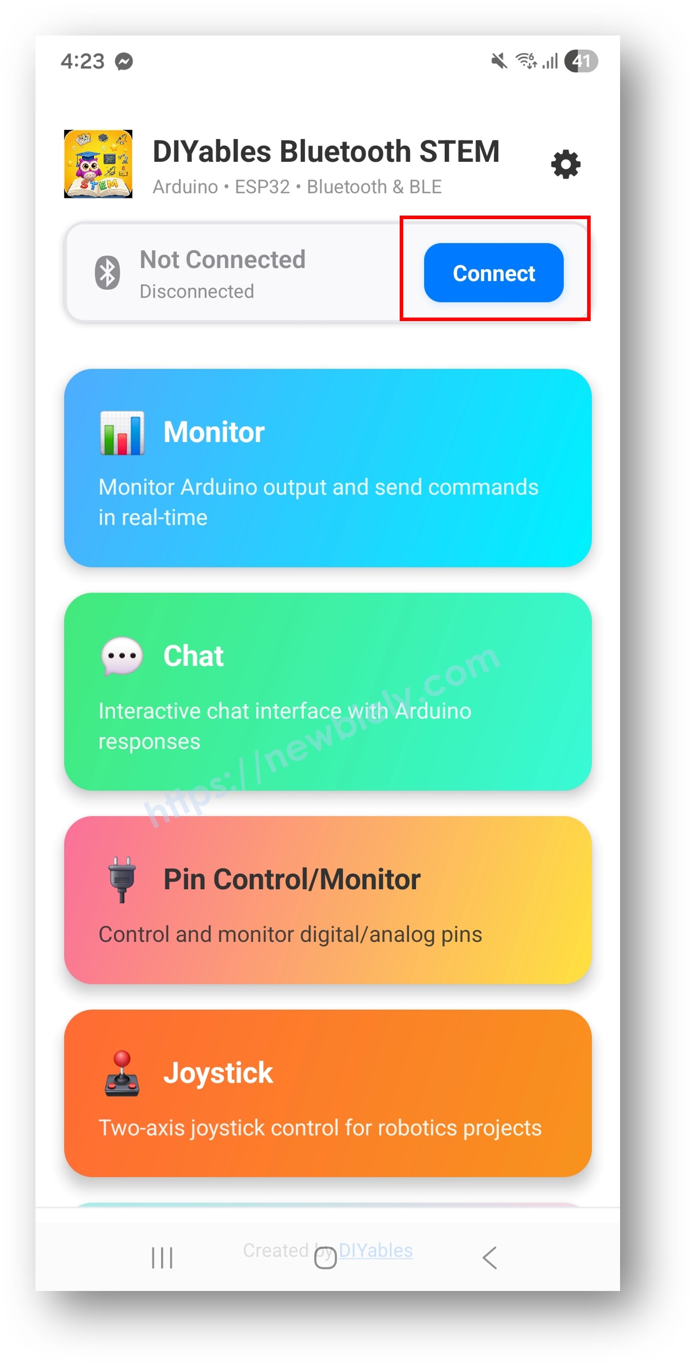
Stellen Sie sicher, dass Bluetooth auf Ihrem Telefon eingeschaltet ist
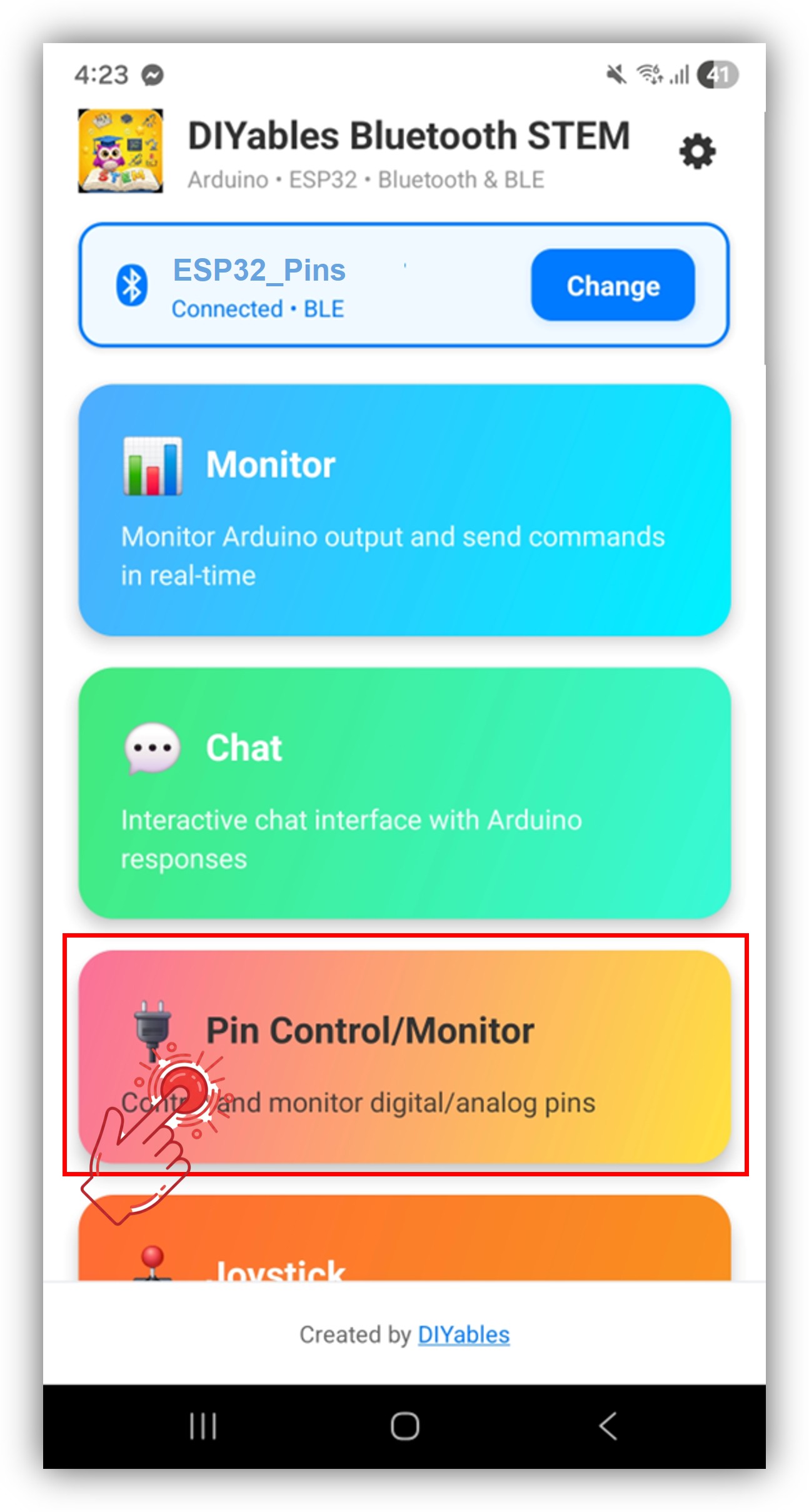
Tippen Sie auf dem Startbildschirm auf Connect. Die App sucht nach BLE- und Classic Bluetooth-Geräten.
Finden und tippen Sie auf Ihr Gerät in den Suchergebnissen, um eine Verbindung herzustellen:
Für Classic Bluetooth: tippen Sie auf "ESP32_Pins"
Für BLE: tippen Sie auf "ESP32BLE_Pins"
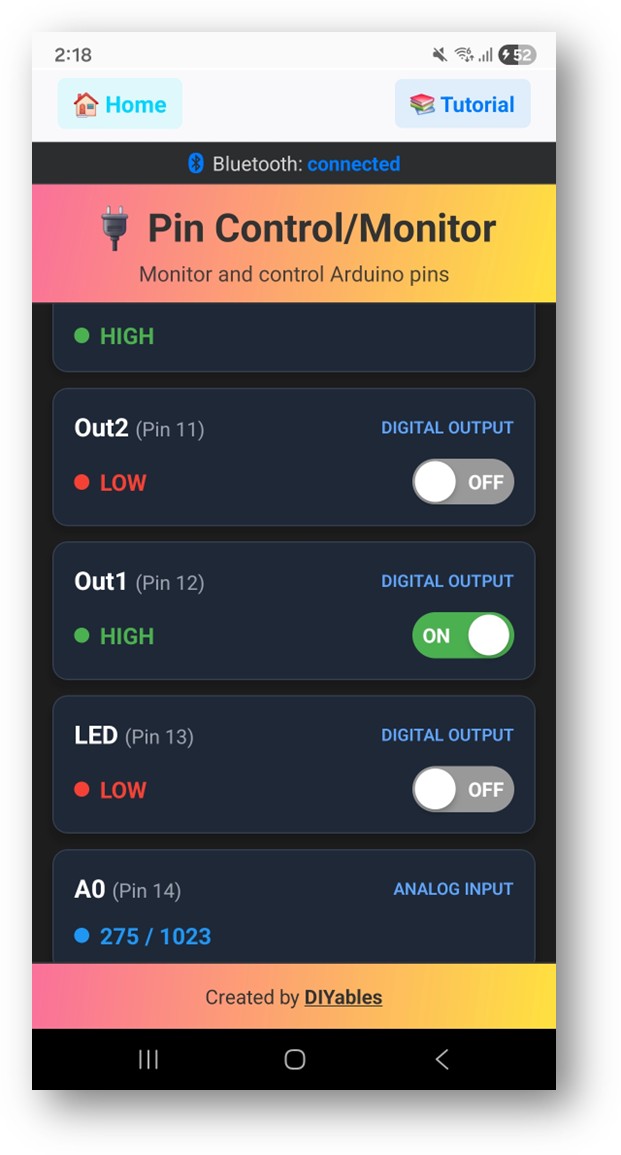
Nach der Verbindung kehrt die App automatisch zum Startbildschirm zurück. Wählen Sie die Digital Pins App aus dem App-Menü.
Hinweis: Sie können das Einstellungssymbol auf dem Startbildschirm antippen, um Apps auf dem Startbildschirm ein-/auszublenden. Weitere Details finden Sie im DIYables Bluetooth App Benutzerhandbuch.
Schalten Sie Ausgangs-Pins durch Antippen um und beobachten Sie, wie sich Eingangs-Pins in Echtzeit aktualisieren
Schauen Sie nun zurück zum Serial Monitor in der Arduino IDE. Sie werden sehen:
Newbiely | Arduino IDE 2.3.8
──
☐
✕
File
Edit
Sketch
Tools
Help
ESP32 Dev Module
Newbiely.ino
···
8Serial.println("Hello World!");
Output
Serial Monitor
Message (Enter to send message to 'ESP32 Dev Module' on 'COM15')
New Line
9600 baud
Bluetooth connected!
Pin 2 set to HIGH
Pin 16 set to LOW
Input pin 18 changed to LOW
Analog pin 34 changed to 2048
Ln 11, Col 1
ESP32 Dev Module on COM15
2
Schalten Sie Pins in der App um und beobachten Sie das Echtzeit-Feedback im Serial Monitor
Kreative Anpassung - Code an Ihr Projekt anpassen
Pins konfigurieren
Aktivieren Sie Pins mit benutzerdefinierten Namen und Modi:
Verwenden Sie den onPinWrite() Callback, um Hardware zu steuern, wenn die App einen Pin umschaltet:
bluetoothPins.onPinWrite([](int pin, int state) {digitalWrite(pin, state);Serial.print("Pin ");Serial.print(pin);Serial.print(" set to ");Serial.println(state ? "HIGH" : "LOW");});
Pin-Read-Befehle behandeln
Verwenden Sie den onPinRead() Callback, um Pin-Zustände an die App zurückzugeben:
bluetoothPins.onPinRead([](int pin) -> int {if (pin == 34 || pin == 35) {// Analog-Wert für ADC-Pins lesenreturnanalogRead(pin); } else {// Digital-Wert für andere Pins lesenreturndigitalRead(pin); }});
Pin-Modus-Änderungen behandeln
Verwenden Sie den onPinModeChange() Callback, um Pin-Modi dynamisch zu ändern:
Sie können gerne den Link zu diesem Tutorial teilen. Bitte verwenden Sie jedoch unsere Inhalte nicht auf anderen Websites. Wir haben viel Mühe und Zeit in die Erstellung der Inhalte investiert, bitte respektieren Sie unsere Arbeit!