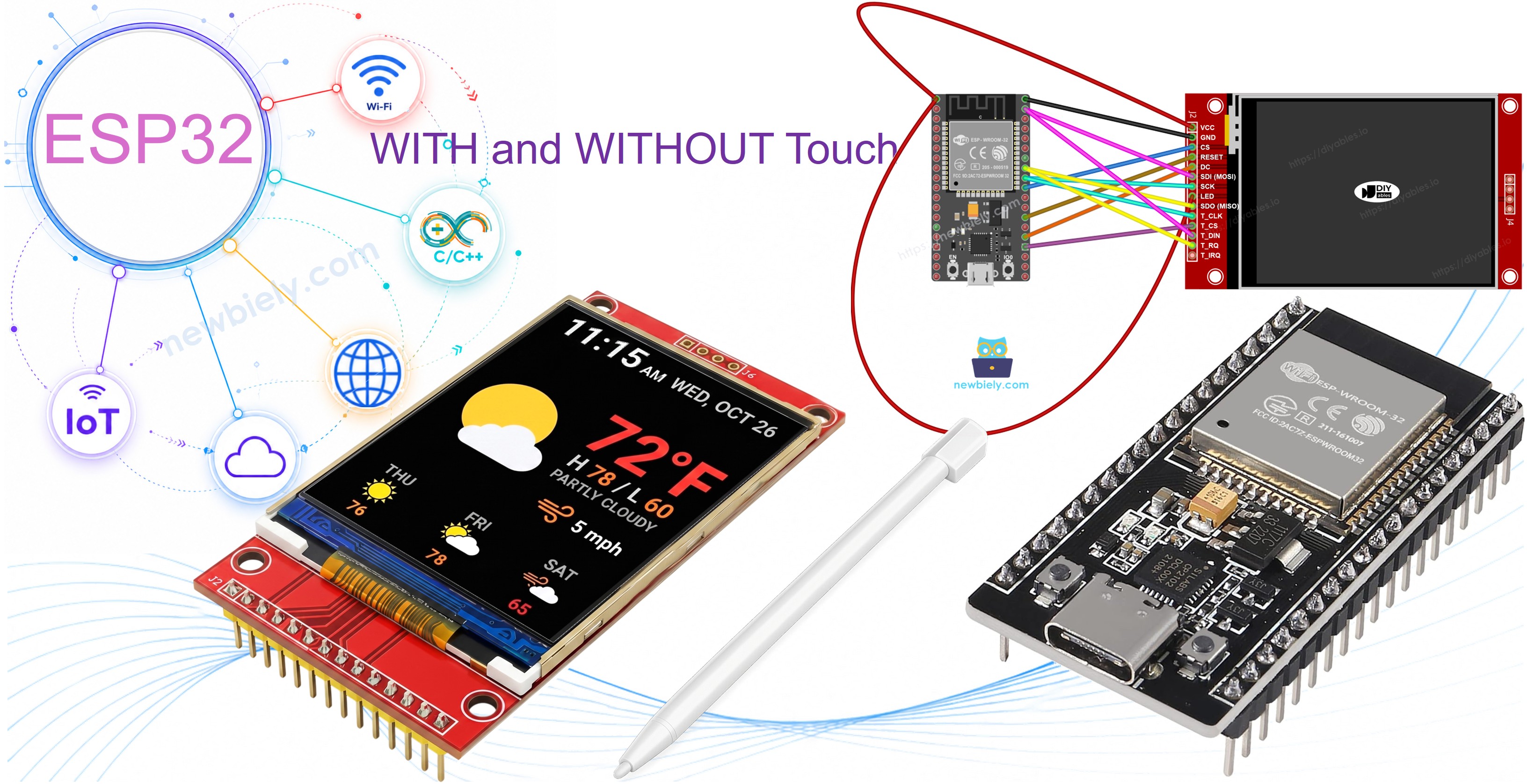
ESP32 - ILI9341 ILI9488 ST7789 TFT LCD Touchscreen-Display SPI-Schnittstelle
Lassen Sie uns ein Projekt aufbauen, das ein Farb-SPI-TFT-Display zum Leben auf einem ESP32 erweckt. Der ESP32 ist ein starker Dual-Core-Mikrocontroller mit Wi-Fi, Bluetooth und vielen GPIO-Pins - und sein VSPI-Hardware-SPI-Bus macht es einfach, ein hochfrequentes TFT-Display mit den vom Panel unterstützten Raten zu betreiben.
Was wir bauen werden:
- Eine verdrahtete Verbindung zwischen einem ESP32 und einem SPI-TFT-Display.
- Eine Shapes-Demo mit der Adafruit GFX-Zeichen-API.
- Ein Beispiel für Text- und Zahlenausgabe.
- Ein Bitmap-Bildanzeiger, der aus dem Programmspeicher (PROGMEM) liest.
- Ein Bitmap-Bildanzeiger, der Bilder von einer SD-Karte liest.
- Eine Demo für benutzerdefinierte externe Schriftarten.
- Ein Touch-Koordinatenlese-Tool mit XPT2046-Controller.
- Eine Touch-Draw-Anwendung (Finger-Malen auf dem Bildschirm).
- Eine interaktive Touch-Button-Oberfläche.
- Ein Touchscreen-Kalibrierungstool.
- Ein benutzerdefiniertes SPI-Bus-Beispiel mit ESP32 HSPI.
Dieses Projekt behandelt sowohl Touch- als auch Non-Touch-SPI-TFT-LCD-Displays. Es funktioniert mit 1,3, 1,54, 2,2, 2,4, 2,8, 3,2 und 3,5 Zoll Panels mit ILI9341-, ILI9488- oder ST7789-Controller-Chips.
Erforderliche Hardware
Oder Sie können die folgenden Kits kaufen:
| 1 | × | DIYables ESP32 Starter-Kit (ESP32 enthalten) | |
| 1 | × | DIYables Sensor-Kit (18 Sensoren/Displays) |
Was ist das SPI-TFT-Display?
Ein SPI-TFT-Modul kombiniert ein LCD-Farbdisplay mit einem Driver-IC, der Zeichenbefehle über einen 4-Draht-SPI-Bus akzeptiert. Die Bibliothek unterstützt drei gängige Chips:
- ILI9341 - 16-Bit-RGB565-Farbe, bis zu 40 MHz SPI.
- ILI9488 - 18-Bit-RGB666-Farbe über SPI, bis zu 24 MHz.
- ST7789 - 16-Bit-RGB565-Farbe, bis zu 40 MHz SPI.
Empfehlung: Wenn Sie ein Display noch nicht gekauft haben, empfehlen wir den ST7789-Driver. Er ist weit verbreitet, läuft mit voller 40-MHz-SPI-Geschwindigkeit und ist die beste Wahl für neue Projekte.
Das Zeichnen wird über die Adafruit GFX-API durchgeführt, die Formen, Text, benutzerdefinierte Schriftarten und Bitmap-Ausgabe umfasst.
Hinweis: Der ESP32 verwendet 3,3V-Logik. Die meisten SPI-TFT-Module arbeiten mit 3,3V. Überprüfen Sie die Spannungsvorgabe Ihres Moduls vor dem Verdrahten.
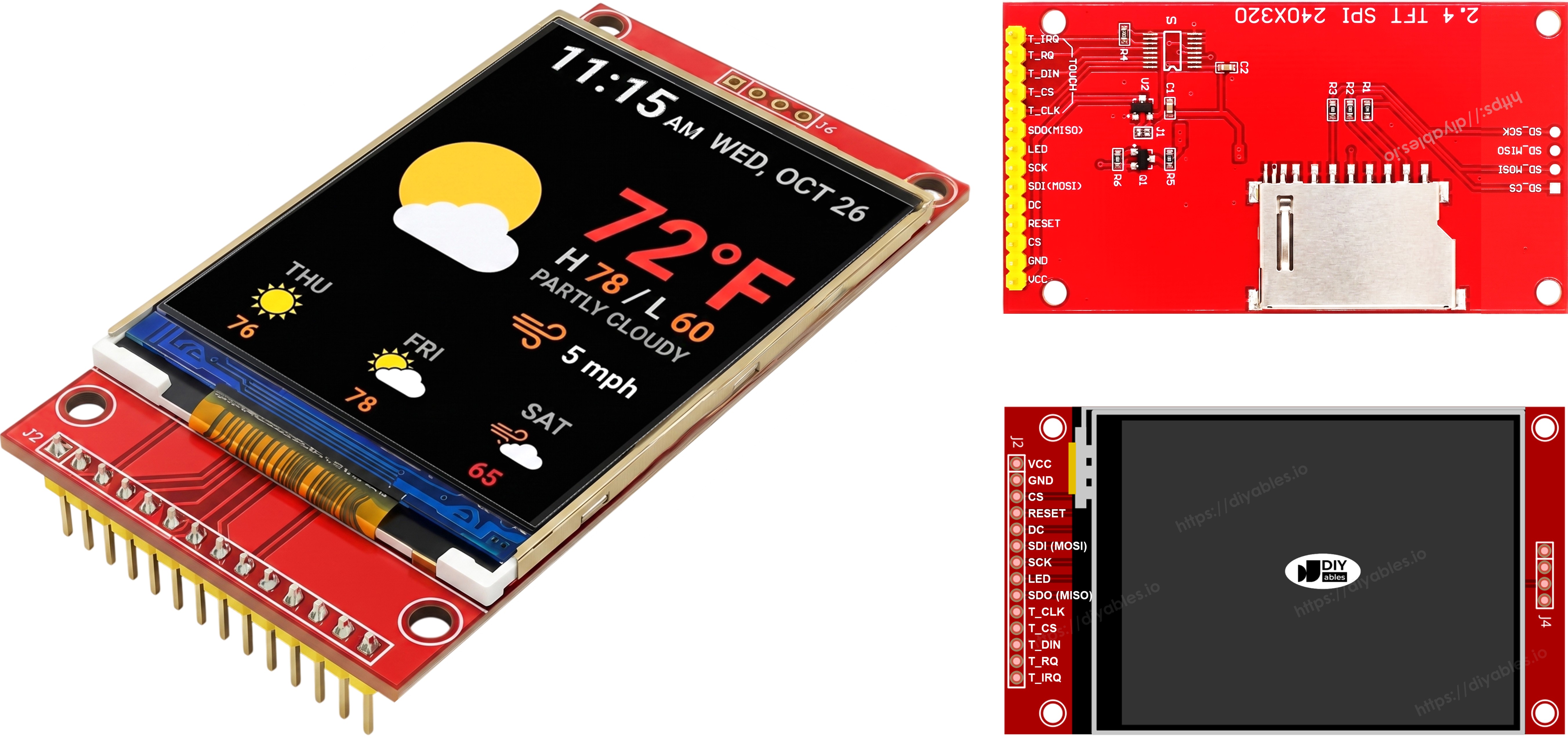
Pinbelegung
Die meisten SPI-TFT-LCD-Displays haben die folgenden Pins:
Display-Pins:
| Pin | Funktion |
|---|---|
| VCC | Stromversorgung |
| GND | Masse |
| CS | Chip Select - wird auf Low gezogen, um das Display auf dem SPI-Bus auszuwählen |
| DC / RS | Daten- / Befehlsauswahl - High für Pixeldaten, Low für Befehle |
| RST | Hardware-Reset - optional; mit 3,3V verbinden, falls nicht verwendet |
| MOSI / SDI / SDA | SPI-Dateneingabe (MCU → Display) |
| SCK / CLK | SPI-Taktsignal |
| MISO / SDO | SPI-Datenausgang (Display → MCU) - optional für reine Displaynutzung |
| LED / BL / BLK | Backlight-Stromversorgung - mit 3,3V oder einem PWM-Pin für Helligkeitssteuerung verbinden |
SD-Karten-Pins (falls Ihre Anwendung auf die SD-Karte zugreifen muss):
| Pin | Funktion |
|---|---|
| SD_CS / TF_CS | SD-Karten-Chip-Select |
| MOSI / SDI | MOSI - Daten vom MCU zur SD-Karte |
| SCK / CLK | SCK - SPI-Taktsignal |
| MISO / SDO | MISO - Daten von der SD-Karte zum MCU |
Für TFT-Displays mit Touch-Unterstützung gibt es zusätzliche Touch-Pins (falls Ihre Anwendung die Touch-Funktion nutzt und das Display sie unterstützt):
| Pin | Funktion |
|---|---|
| T_CS | Touch-Controller-Chip-Select |
| T_CLK | SCK - SPI-Taktsignal |
| T_DIN | MOSI - Daten vom MCU zum Touch-Controller |
| T_DO | MISO - Daten vom Touch-Controller zum MCU |
| T_IRQ | Touch-Interrupt - optional; signalisiert, wenn der Bildschirm berührt wird |
Hinweis: Einige Non-Touch-Display-Module zeigen auch T_CS-, T_CLK-, T_DIN-, T_DO- und T_IRQ-Pins. Diese sind auf diesen Platinen nicht funktionsfähig - der Touch-Controller-IC ist nicht bestückt. Sie erscheinen, weil die Platine das gleiche Layout wie die Touch-aktivierte Version verwendet, um Herstellungsvarianten zu reduzieren.
Verdrahtungsschema
Ohne Touch
Verbinden Sie MOSI mit GPIO23, SCK mit GPIO18 und MISO mit GPIO19 auf dem ESP32. CS, DC und RST können beliebige verfügbare GPIO sein - GPIO5, GPIO2, GPIO4 werden in den Beispielen verwendet.
Display:
| TFT-Pin | ESP32-Pin | Beschreibung |
|---|---|---|
| VCC | 3.3V | Stromversorgung (nur 3,3V) |
| GND | GND | Masse |
| CS | GPIO5 | Chip Select |
| DC / RS | GPIO2 | Daten- / Befehlsauswahl |
| RST | GPIO4 | Reset (optional) |
| MOSI / SDI | GPIO23 | Hardware-SPI-MOSI (VSPI) |
| SCK | GPIO18 | Hardware-SPI-Taktsignal (VSPI) |
| MISO / SDO | GPIO19 | Hardware-SPI-MISO (VSPI, optional) |
| LED / BL | 3.3V | Backlight-Stromversorgung |
SD-Karte (falls Ihre Anwendung auf die SD-Karte zugreifen muss):
| SD-Pin | ESP32-Pin | Beschreibung |
|---|---|---|
| SD_CS / TF_CS | beliebiger freier GPIO | SD-Karten-Chip-Select |
| MOSI / SDI | GPIO23 | Mit Display-MOSI geteilt (GPIO23) |
| SCK / CLK | GPIO18 | Mit Display-SCK geteilt (GPIO18) |
| MISO / SDO | GPIO19 | Mit Display-MISO geteilt (GPIO19) |
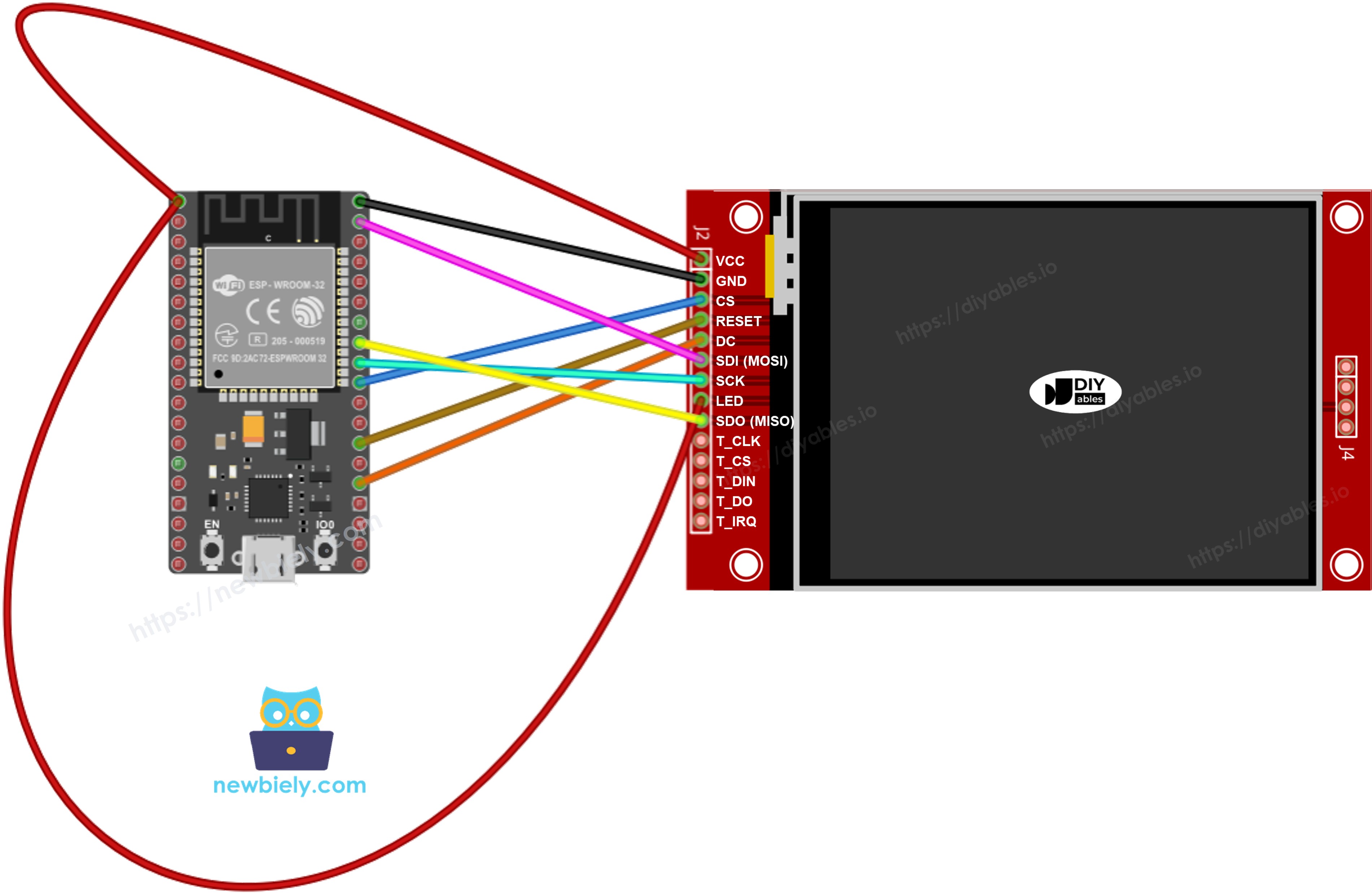
Dieses Bild wurde mit Fritzing erstellt. Klicken Sie, um das Bild zu vergrößern.
Wenn Sie nicht wissen, wie Sie ESP32 und andere Komponenten mit Strom versorgen, finden Sie Anleitungen im folgenden Tutorial: Wie man ESP32 mit Strom versorgt.
Hinweis: Das obige Diagramm zeigt die korrekte Verdrahtung. In der Praxis ist es nicht einfach, zwei Drähte in das gleiche ESP32-Pin-Header-Loch zu stecken. Eine praktische Lösung ist die Verwendung eines Schraubklemmen-Breakout-Boards für ESP32 - zwei Drähte können in die gleiche Schraubklemme gesichert werden, oder ein Draht in die Schraube und einer im angrenzenden Header-Pin.
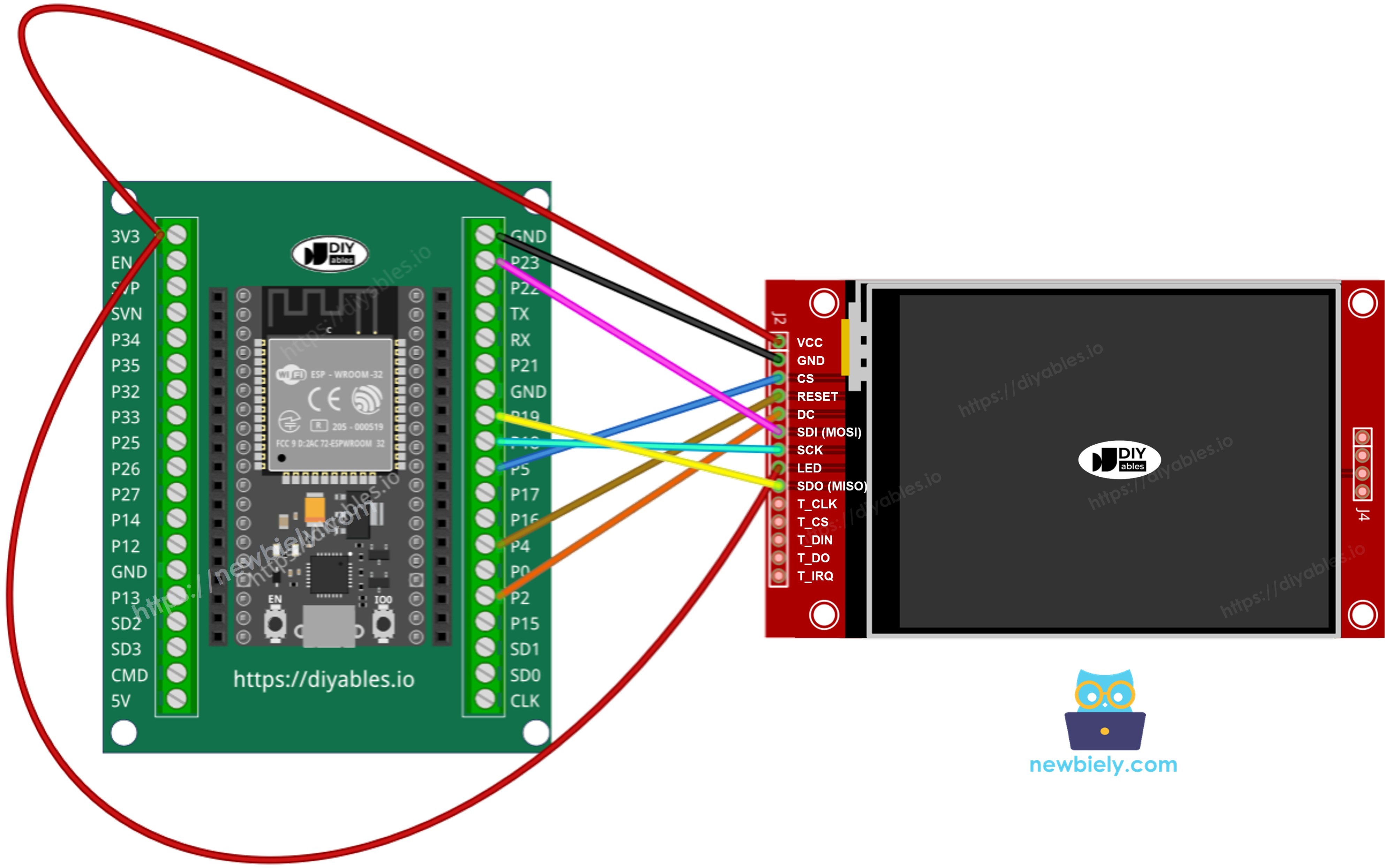
Dieses Bild wurde mit Fritzing erstellt. Klicken Sie, um das Bild zu vergrößern.
Mit Touch
Verbinden Sie den XPT2046-Touch-Controller mit dem ESP32-VSPI-Bus und teilen Sie GPIO23, GPIO18 und GPIO19 mit dem Display.
Display:
| TFT-Pin | ESP32-Pin | Beschreibung |
|---|---|---|
| VCC | 3.3V | Stromversorgung (nur 3,3V) |
| GND | GND | Masse |
| CS | GPIO5 | Chip Select |
| DC / RS | GPIO2 | Daten- / Befehlsauswahl |
| RST | GPIO4 | Reset (optional) |
| MOSI / SDI | GPIO23 | Hardware-SPI-MOSI (VSPI) |
| SCK | GPIO18 | Hardware-SPI-Taktsignal (VSPI) |
| MISO / SDO | GPIO19 | Hardware-SPI-MISO (VSPI, optional) |
| LED / BL | 3.3V | Backlight-Stromversorgung |
Touch-Controller (falls Ihre Anwendung die Touch-Funktion nutzt und das Display sie unterstützt):
| Touch-Pin | ESP32-Pin | Beschreibung |
|---|---|---|
| T_CS | beliebiger freier GPIO | Touch-Chip-Select |
| T_IRQ | beliebiger freier GPIO | Touch-Interrupt (optional) |
| T_DIN | GPIO23 | Mit Display-MOSI geteilt (GPIO23) |
| T_CLK | GPIO18 | Mit Display-SCK geteilt (GPIO18) |
| T_DO | GPIO19 | Mit Display-MISO geteilt (GPIO19) |
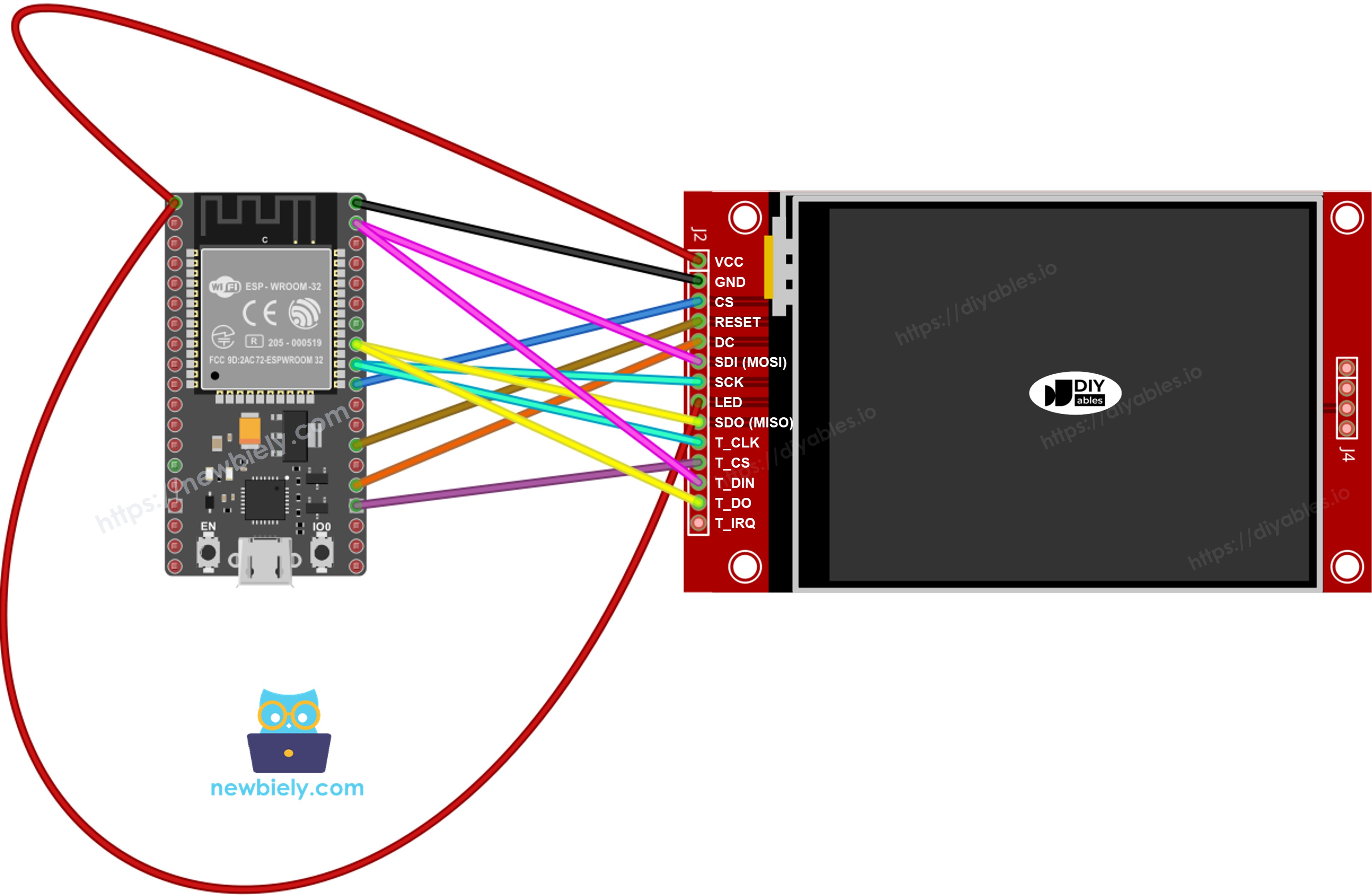
Dieses Bild wurde mit Fritzing erstellt. Klicken Sie, um das Bild zu vergrößern.
Hinweis: Das obige Diagramm zeigt die korrekte Verdrahtung. In der Praxis ist es nicht einfach, zwei Drähte in das gleiche ESP32-Pin-Header-Loch zu stecken. Eine praktische Lösung ist die Verwendung eines Schraubklemmen-Breakout-Boards für ESP32 - zwei Drähte können in die gleiche Schraubklemme gesichert werden, oder ein Draht in die Schraube und einer im angrenzenden Header-Pin.
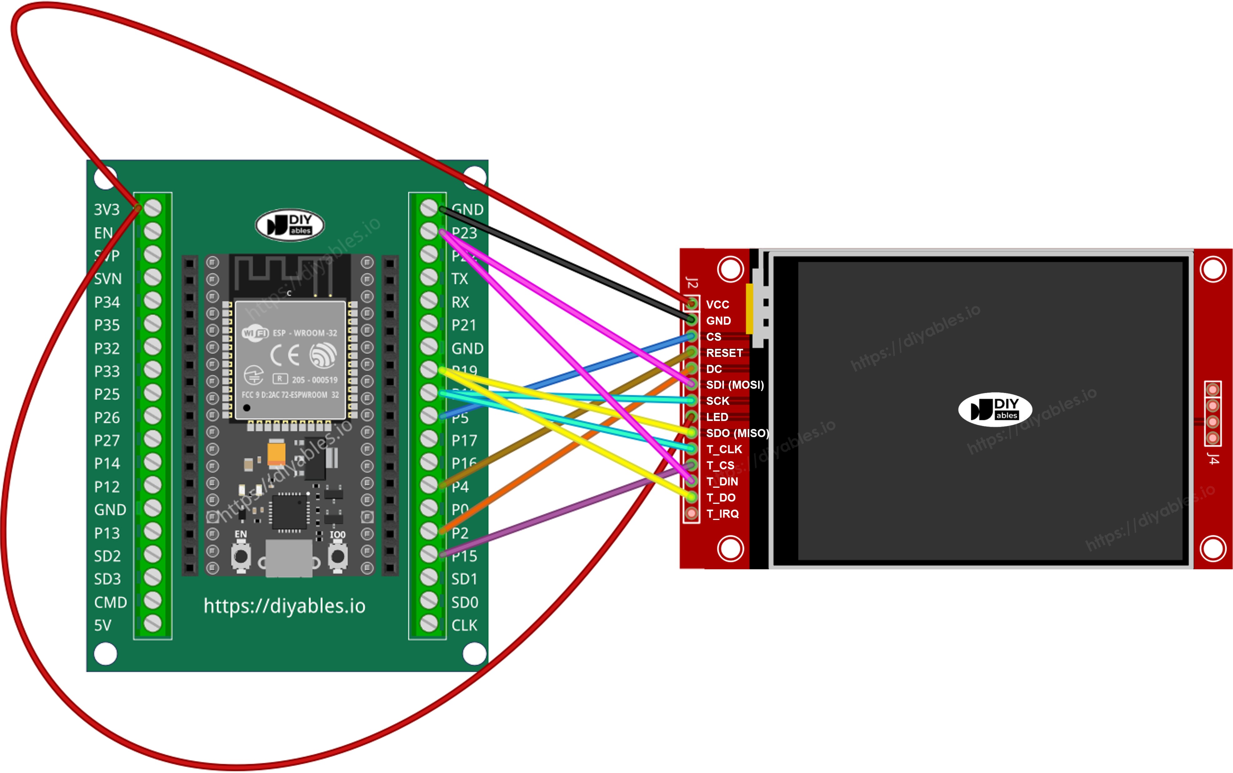
Dieses Bild wurde mit Fritzing erstellt. Klicken Sie, um das Bild zu vergrößern.
Wenn Ihr MCU zwei oder mehr Hardware-SPI-Schnittstellen hat, können Sie jeden peripheren Geräte (Display, SD-Karte, Touch-Controller) an seinen eigenen dedizierten SPI-Bus anschließen. Wenn Ihr MCU nur eine Hardware-SPI-Schnittstelle hat, teilen alle drei peripheren Geräte die gleichen drei Datenleitungen (MOSI, SCK, MISO) - auf dem ESP32 sind dies GPIO23, GPIO18 und GPIO19. Jedes Gerät hat seinen eigenen CS-Pin, so dass nur eines aktiv ist. Die DIYables_TFT_SPI-Bibliothek verwaltet sowohl das Display als auch den XPT2046-Touch-Controller über eine einzige API - es wird keine separate SPI-Bibliothek für die Touch-Seite benötigt.
Bibliotheksinstallation
- Verbinden Sie das ESP32-Board über seinen USB-C-Port mit Ihrem Computer.
- Öffnen Sie die Arduino IDE. Wählen Sie Ihre ESP32-Board-Variante aus dem Board-Menü und wählen Sie den richtigen COM-Port.
- Öffnen Sie das Libraries Panel.
- Suchen Sie nach "DIYables_TFT_SPI". Suchen Sie den DIYables-Eintrag.
- Klicken Sie auf Install und akzeptieren Sie alle Abhängigkeitsinstallationen.
- Search for DIYables TFT SPI created by DIYables.io and click the Install button.
Projektgrundlage
Der Basis-Sketch für jedes ESP32-TFT-Projekt mit dieser Bibliothek:
Lassen Sie uns bauen - Formen zeichnen
Das DrawShapes-Beispiel zeichnet die vollständige Palette von Adafruit GFX-Primitiven: Kreise, Dreiecke, Rechtecke, gerundete Rechtecke und Linien.
Hochladen und Testen
- Verdrahten Sie das TFT-Modul mit dem ESP32 mit der obigen Tabelle.
- Stecken Sie das USB-C-Kabel ein.
- Fügen Sie in der Arduino IDE den Code ein, wählen Sie das Board und den Port aus, und drücken Sie Upload.
- Nach dem Hochladen füllt sich das Display mit einer Schleife farbiger Formen.
Zeichnungs-API-Referenz
| Methode | Zweck | Verwendung |
|---|---|---|
| begin() | Initialisiert das Display. | TFT_display.begin(); |
| setRotation(r) | Stellt die Bildschirmorientierung 0-3 ein. | TFT_display.setRotation(1); |
| fillScreen(color) | Füllt den gesamten Bildschirm mit einer Farbe. | TFT_display.fillScreen(BLACK); |
| colorRGB(r,g,b) | Erstellt einen 16-Bit-Farbwert. | colorRGB(255,128,0) |
| fillCircle(x,y,r,color) | Vollständig gefüllter Kreis. | TFT_display.fillCircle(120,160,60,RED); |
| fillRect(x,y,w,h,color) | Volles Rechteck. | TFT_display.fillRect(0,0,100,50,BLUE); |
| drawLine(x0,y0,x1,y1,color) | Gerade Linie zwischen zwei Punkten. | TFT_display.drawLine(0,0,320,240,WHITE); |
Lassen Sie uns bauen - Text und Zahlen anzeigen
Das ShowTextAndNumber-Beispiel verwendet die Adafruit GFX-Text-Engine zum Drucken von Zeichenketten und numerischen Werten in verstellbaren Größen und Farben.
Hochladen und Testen
- Verdrahten und hochladen wie oben.
- Das Display zeigt mehrere Textzeilen und Zahlen in verschiedenen Farben und Größen.
Zeichnungs-API-Referenz
| Methode | Zweck | Verwendung |
|---|---|---|
| setTextColor(color) | Stellt die Vordergrundfarbe des Textes ein. | TFT_display.setTextColor(WHITE); |
| setTextSize(size) | Skaliert Text. Größe 1 = 6×8 px, Größe 2 = 12×16 px. | TFT_display.setTextSize(2); |
| setCursor(x, y) | Platziert den Text-Cursor bei Pixel (x, y). | TFT_display.setCursor(10, 20); |
| print(value) | Druckt eine Zeichenkette oder Zahl am Cursor. | TFT_display.print("ESP32!"); |
| println(value) | Druckt und bewegt den Cursor zur nächsten Zeile. | TFT_display.println(42); |
Lassen Sie uns bauen - Bild zeichnen
Lassen Sie uns einen Bild-Viewer erstellen. Das DrawImage-Beispiel lädt ein Vollfarb-RGB565-Bitmap aus dem ESP32-Flash in den Speicher und rendert es auf dem Display. Die Pixeldaten werden in bitmap.h als ein const uint16_t Array mit PROGMEM deklariert. Auf dem ESP32 werden PROGMEM-Daten aus dem Flash in den virtuellen Adressraum abgebildet, sodass sich das Bild zeichnet, ohne RAM zu verbrauchen.
Kopieren Sie bitmap.h in den Sketch-Ordner, bevor Sie kompilieren.
Hochladen und Testen
- Platzieren Sie bitmap.h im gleichen Ordner wie den Sketch.
- Verdrahten Sie das TFT-Modul mit dem ESP32 wie oben gezeigt (MOSI=GPIO23, SCK=GPIO18, MISO=GPIO19, CS=GPIO5, DC=GPIO2, RST=GPIO4). Verwenden Sie 3,3V für VCC.
- Stecken Sie das USB-C-Kabel ein.
- Wählen Sie in der Arduino IDE das Board und den Port aus, und drücken Sie Upload.
- Das Display rendert das Bitmap-Bild aus dem Flash.
Zeichnungs-API-Referenz
| Methode | Zweck | Verwendung |
|---|---|---|
| drawRGBBitmap(x,y,bitmap,w,h) | Zeichnet ein RGB565-PROGMEM-Bitmap mit der oberen linken Ecke bei (x, y). | TFT_display.drawRGBBitmap(0, 0, myImage, 240, 320); |
| fillScreen(color) | Löscht das Display, bevor das Bild gezeichnet wird. | TFT_display.fillScreen(BLACK); |
Lassen Sie uns bauen - SD-Kartenbild zeichnen
Lassen Sie uns einen SD-Kartenbilds-Viewer erstellen. Das DrawImageSDcard-Beispiel liest ein rohes RGB565-Binär-Bild von einer Micro-SD-Karte und streamt die Pixeldaten in Chunks zum Display. Der ESP32 verwaltet sowohl die SD-Karte als auch das Display auf dem gleichen VSPI-Bus, wobei die CS-Leitungen zwischen ihnen umgeschaltet werden.
Verdrahten Sie das SD-Modul mit GPIO23 (MOSI), GPIO18 (SCK), GPIO19 (MISO). Definieren Sie einen separaten CS-Pin für das SD-Modul als SD_CS_PIN im Sketch.
Hochladen und Testen
- Verdrahten Sie das SD-Modul mit dem ESP32-VSPI-Bus. Teilen Sie GPIO23/18/19 mit dem Display. Verbinden Sie SD CS mit dem als SD_CS_PIN definierten Pin.
- Kopieren Sie eine rohes RGB565-Binär-Bilddatei in das Root-Verzeichnis der SD-Karte. Die Dimensionen müssen Ihrem Panel entsprechen.
- Stecken Sie das USB-C-Kabel ein.
- Wählen Sie in der Arduino IDE das Board und den Port aus, und drücken Sie Upload.
- Das Display rendert das Bild, das von der SD-Karte gestreamt wird.
Zeichnungs-API-Referenz
| Methode | Zweck | Verwendung |
|---|---|---|
| startWrite() | Öffnet eine direkte SPI-Schreib-Sitzung und behauptet den Display-CS. | TFT_display.startWrite(); |
| setAddrWindow(x0,y0,x1,y1) | Definiert den rechteckigen Pixel-Schreib-Bereich auf dem Panel. | TFT_display.setAddrWindow(0, 0, 239, 319); |
| pushColors(buf, len) | Sendet einen Puffer von RGB565-Pixelwerten zum Display. | TFT_display.pushColors(buf, 512); |
| endWrite() | Schließt die SPI-Sitzung und gibt den Display-CS frei. | TFT_display.endWrite(); |
Lassen Sie uns bauen - Externe Schriftart verwenden
Lassen Sie uns einen benutzerdefinierten Text-Display erstellen. Das UseExternalFont-Beispiel ersetzt die Standard-5×7-Pixel-Schriftart durch eine schärfere Adafruit GFX-kompatible Outline-Schriftart. Ein Aufruf von setFont() ist alles, was es braucht, um die Typografie zu verbessern. Der Aufruf von setFont(NULL) stellt die ursprüngliche eingebaute Schriftart jederzeit wieder her.
Hochladen und Testen
- Verdrahten Sie das TFT-Modul mit dem ESP32 wie oben gezeigt.
- Stecken Sie das USB-C-Kabel ein.
- Wählen Sie in der Arduino IDE das Board und den Port aus, und drücken Sie Upload.
- Das Display rendert Text in der benutzerdefinierten Schriftart.
Zeichnungs-API-Referenz
| Methode | Zweck | Verwendung |
|---|---|---|
| setFont(&FontName) | Aktiviert eine benutzerdefinierte GFX-kompatible Schriftart. Übergeben Sie NULL, um die eingebaute 5×7-Schriftart wiederherzustellen. | TFT_display.setFont(&FreeSans12pt7b); |
| setCursor(x, y) | Positioniert den Text-Cursor bei der angegebenen Pixel-Koordinate. | TFT_display.setCursor(10, 40); |
| setTextColor(color) | Stellt die Vordergrundfarbe für nachfolgende Texte ein. | TFT_display.setTextColor(WHITE); |
| print(text) | Druckt eine Zeichenkette am Cursor mit der aktiven Schriftart. | TFT_display.print("ESP32 Project"); |
Lassen Sie uns bauen - Touch-Punkt auslesen
Lassen Sie uns einen Touch-Koordinatenlese-Tool erstellen. Das TouchGetPoint-Beispiel initialisiert den XPT2046 auf dem ESP32-VSPI-Bus und druckt rohe ADC-Werte in den Serial Monitor, wenn der Bildschirm gedrückt wird. Dies ist der erste Schritt zu einem Touch-fähigen Projekt: Das Verständnis des Rohdaten-Bereichs, den Ihr Panel produziert.
Verdrahtung (alle Signale bei 3,3V):
| Touch-Pin | ESP32-Pin | Beschreibung |
|---|---|---|
| T_CLK | GPIO18 | SCK - mit Display geteilt |
| T_DIN | GPIO23 | MOSI - mit Display geteilt |
| T_DO | GPIO19 | MISO - mit Display geteilt |
| T_CS | GPIO15 | Touch-Chip-Select |
| T_IRQ | GPIO27 | Touch-Interrupt (optional) |
Hochladen und Testen
- Verdrahten Sie den XPT2046 mit dem ESP32-VSPI-Bus, teilen Sie GPIO23/18/19 mit dem Display. T_CS→GPIO15, T_IRQ→GPIO27.
- Stecken Sie das USB-C-Kabel ein.
- Wählen Sie in der Arduino IDE das Board und den Port aus, und drücken Sie Upload.
- Öffnen Sie den Serial Monitor bei 9600 Baud. Berühren Sie das Display, um rohe X-, Y- und Z-Werte gedruckt zu sehen.
Zeichnungs-API-Referenz
| Methode | Zweck | Verwendung |
|---|---|---|
| initTouchSPI(cs, irq) | Initialisiert den XPT2046 auf dem gemeinsamen SPI-Bus. Übergeben Sie -1 für irq, wenn der Interrupt-Pin nicht verbunden ist. | TFT_display.initTouchSPI(14, 27); |
| readTouchRaw(x, y, z) | Gibt rohe ADC-Werte vom Controller ohne Kalibrierung zurück. Gibt true zurück, wenn gedrückt. | TFT_display.readTouchRaw(x, y, z); |
Lassen Sie uns bauen - Touch-Draw
Lassen Sie uns eine Finger-Mal-App erstellen. Das TouchDraw-Beispiel kombiniert den XPT2046-Touch-Controller mit der Zeichnungs-API des Displays. Jede Touchposition wird auf eine kalibrierte Pixel-Koordinate abgebildet und ein kleiner gefüllter Kreis wird dort gezeichnet, wodurch ein Strich entsteht, wenn der Finger bewegt wird.
Hochladen und Testen
- Verdrahten Sie den XPT2046 mit dem ESP32 wie im Abschnitt Touch Get Point beschrieben.
- Stecken Sie das USB-C-Kabel ein.
- Wählen Sie in der Arduino IDE das Board und den Port aus, und drücken Sie Upload.
- Ziehen Sie einen Finger über das Display, um auf dem Bildschirm zu malen.
Zeichnungs-API-Referenz
| Methode | Zweck | Verwendung |
|---|---|---|
| initTouchSPI(cs, irq) | Initialisiert den XPT2046 auf dem gemeinsamen VSPI-Bus. | TFT_display.initTouchSPI(14, 27); |
| setTouchCalibration(minX,maxX,minY,maxY) | Ordnet rohe ADC-Werte auf Bildschirm-Pixel-Koordinaten ab. Holen Sie sich die vier Werte aus dem TouchCalibration-Beispiel. | TFT_display.setTouchCalibration(200, 3800, 300, 3700); |
| setTouchInvertX(invert) / setTouchInvertY(invert) | Invertiert die Touch-Achse, wenn X oder Y auf Ihrem spezifischen Panel oder Batch gespiegelt wird. Rufen Sie VOR setTouchCalibration() auf. | TFT_display.setTouchInvertY(true); |
| getTouch(x, y) | Gibt kalibrierte Touch-Koordinaten in Bildschirm-Pixeln zurück. Gibt true zurück, wenn der Bildschirm gedrückt wird. | if (TFT_display.getTouch(x, y)) { ... } |
| fillCircle(x, y, r, color) | Zeichnet einen kleinen Punkt auf der Touchposition, um das Gemälde aufzubauen. | TFT_display.fillCircle(x, y, 3, RED); |
Lassen Sie uns bauen - Touch-Kalibrierung
Lassen Sie uns ein Kalibrierungstool erstellen. Das TouchCalibration-Beispiel führt Sie durch die Messung der rohen ADC-Extreme Ihres XPT2046-Panels. Berühren Sie wie aufgefordert jede Ecke des Displays und notieren Sie die gedruckten minimalen und maximalen X- und Y-Werte. Diese vier Zahlen sind die Konstanten für setTouchCalibration() in allen anderen Touch-Projekten.
Hochladen und Testen
- Verdrahten Sie den XPT2046 mit dem ESP32 wie im Abschnitt Touch Get Point beschrieben.
- Stecken Sie das USB-C-Kabel ein.
- Wählen Sie in der Arduino IDE das Board und den Port aus, und drücken Sie Upload.
- Öffnen Sie den Serial Monitor bei 9600 Baud. Folgen Sie den On-Screen-Anweisungen und berühren Sie jede Ecke.
- Notieren Sie die vier gedruckten Werte und verwenden Sie sie in setTouchCalibration() in Ihren anderen Touch-Projekten.
Zeichnungs-API-Referenz
| Methode | Zweck | Verwendung |
|---|---|---|
| initTouchSPI(cs, irq) | Initialisiert den XPT2046-Touch-Controller. | TFT_display.initTouchSPI(14, 27); |
| readTouchRaw(x, y, z) | Liest rohe ADC-Werte, um den Kalibrierungsbereich zu bestimmen. | TFT_display.readTouchRaw(x, y, z); |
| setTouchCalibration(minX,maxX,minY,maxY) | Speichert Kalibrierungskonstanten, damit getTouch() rohe Werte korrekt auf Pixel-Koordinaten abbildet. | TFT_display.setTouchCalibration(200, 3800, 300, 3700); |
| setTouchInvertX(invert) / setTouchInvertY(invert) | Invertiert die Touch-Achse, wenn X oder Y auf Ihrem spezifischen Panel oder Batch gespiegelt wird. Rufen Sie VOR der Kalibrierung auf, damit die gespeicherten Werte mit Ihrem Panel übereinstimmen. | TFT_display.setTouchInvertY(true); |
Lassen Sie uns bauen - Benutzerdefinierter SPI
Lassen Sie uns auf einem benutzerdefinierten SPI-Bus bauen. Der ESP32 hat zwei Hardware-SPI-Controller: VSPI und HSPI. Das CustomSPI-Beispiel zeigt, wie Sie eine SPIClass-Instanz für den HSPI-Bus erstellen und sie an den Display-Konstruktor übergeben. Dies gibt den VSPI-Bus für andere Peripheriegräte frei, z. B. SD-Karten oder Sensor-Module, die SPI gemeinsam nutzen.
Hochladen und Testen
- Verdrahten Sie das TFT-Display mit den ESP32-HSPI-Pins oder dem benutzerdefinierten SPI-Bus, den Sie im Sketch definieren.
- Stecken Sie das USB-C-Kabel ein.
- Wählen Sie in der Arduino IDE das Board und den Port aus, und drücken Sie Upload.
- Das Display startet auf dem ausgewählten SPI-Bus und zeigt ein Farbbalken-Muster, um den Erfolg zu bestätigen.
Zeichnungs-API-Referenz
| Methode | Zweck | Verwendung |
|---|---|---|
| SPIClass myBus(HSPI) | Erstellt eine SPIClass-Instanz, die an den HSPI-Controller (GPIO14/12/13/15) gebunden ist. | SPIClass HSPI_bus(HSPI); |
| DIYables_ILI9341_SPI(w,h,cs,dc,rst,spi) | Konstruktor, der einen Zeiger auf jede SPIClass akzeptiert. Standardmäßig &SPI (VSPI), wenn weggelassen. | DIYables_ILI9341_SPI tft(240, 320, 5, 2, 4, &HSPI_bus); |
| begin() | Initialisiert das Display auf dem konfigurierten SPI-Bus. | TFT_display.begin(); |
Fehlersuche
| Problem | Ursache | Behebung |
|---|---|---|
| Leerer Bildschirm | Falsche SPI-Pins oder falsche Stromversorgung | Verwenden Sie VSPI-Pins GPIO23/18/19; überprüfen Sie, ob VCC 3,3V ist |
| Verwirrtes Bild | Falscher aktiver Driver | Kommentieren Sie nur den passenden Konstruktor aus |
| Bild versetzt | Breite/Höhe-Nichtübereinstimmung des Konstruktors | Gleichen Sie Werte Ihren tatsächlichen Panel-Abmessungen an |
| Keine Touch-Reaktion | Fehlende Kalibrierungsdaten | Führen Sie das TouchCalibration-Beispiel aus und kopieren Sie die gedruckten Werte |
| Port nicht sichtbar | USB-Treiber fehlt | Installieren Sie CP210x oder CH340 USB-Treiber für Ihr Board |
Plattformunterstützung
Die Bibliothek ist auf der Standard-SPI-API von Arduino aufgebaut und unterstützt alle Arduino-kompatiblen ESP32-Varianten (architectures=*).